AMS104Y Panasonic Electric Works, AMS104Y Datasheet - Page 5
AMS104Y
Manufacturer Part Number
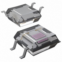
AMS104Y
Description
SENSOR LIGHT NAPICA 5V SMT 4SOP
Manufacturer
Panasonic Electric Works
Datasheet
1.AMS104Y.pdf
(6 pages)
Specifications of AMS104Y
Wavelength
580nm
Output Type
Current
Package / Case
4-SOP
Lead Free Status / RoHS Status
Lead free / RoHS Compliant
Other names
255-1842-2
255-1848-2
255-1848-2
Available stocks
Company
Part Number
Manufacturer
Quantity
Price
Company:

Part Number:
AMS104Y
Manufacturer:
PANASONIC
Quantity:
2 100


5. Recommended soldering
conditions
<SMD/Chip type>
1) Recommended condition
(1) IR (Infrared reflow) soldering method
T
T
T
t
t
(2) Soldering iron method
Tip temperature: 350 to 400°C
752°F
Wattage: 30 to 60 W
Soldering time: within 3 s
*We don’t recommend soldering iron
method for chip type.
2) Do not do flow soldering.
<Through-hole type>
1) Recommended condition
(1) Double wave soldering method
T
T
t
t
(2) Soldering iron method
Tip temperature: 350 to 400°C
752°F
Wattage: 30 to 60 W
Soldering time: within 3 s
11. The following shows the packaging format
1) SMD type tape and reel (mm inch)
1
2
1
2
Light sensor
NaPiCa
SMD type
AMS104Y
1
2
3
1
2
+t
= 60 to 120 s or less
= 30 s or less
= 120 s or less
= 150 to 180°C
= 230°C
= 250°C
= 120°C
= 260°C
3
T
T
T
T
T
= 6 s or less
3
2
1
2
1
Type
446°F
482°F
248°F
500°F
Note) When picked from 1 and 4-pin side
.059
.008
1.5
0.2
±.012
t
t
±0.3
1
1
or less
or less
302 to 356°F
±0.05
±.002
(Please inquire for tape and reel packaging with 2-pin and 3-pin on the
pull-out side.)
Anode side
Cathode side
.142
.094
3.6
2.4
t
2
t
2
±0.1
Device
mounted
on tape
±.004
±.004
±0.1
t
3
662 to
662 to
All Rights Reserved © COPYRIGHT Panasonic Electric Works Co., Ltd.
.157
.157
4.0
4.0
Tape dimensions
±.004
±0.1
±.004
±0.1
2) The soldered position on leads should
not be closer than 3mm
molding resin of this sensor.
6. Notes for mounting
1) Temperature rise in the lead portion is
highly dependent on package size.
If multiple different packages are
mounted on the same board, please
check your board beforehand in an actual
product, ensuring that the temperature of
the solder area of the sensor terminals
falls within the temperature conditions of
item 5.
2) If the mounting conditions exceed the
recommended solder conditions in item
5, resin strength will fall and the
mismatching of the heat expansion
coefficient of each constituent material
will increase markedly, possibly causing
cracks in the package, disconnections of
bonding wires, and the like. For this
reason, please inquire with us about
whether this use is possible.
7. Cleaning solvents compatibility
We recommend dip cleaning with an
organic solvent for removal of solder flux
etc. If you cannot avoid using ultrasonic
cleansing, please ensure that the
following conditions are met, and check
beforehand for defects.
• Frequency: 27 to 29 kHz
• Ultrasonic power: No greater than
• Cleaning time: No longer than 30 s
• Cleanser used: Asahiklin AK-225
• Other:
Note: Applies to unit area ultrasonic power for
0.25W/cm
Submerge in solvent in order to prevent
the PCB and sensors from being
contacted directly by the ultrasonic
vibrations.
Direction of
picking
ultrasonic baths.
2.0
.079
1.0
.039
±0.1
±.004
±0.1
±.004
2
dia.
dia.
1.5
.059
+0.1
−0
+.004
−0
1.75
.069
3.5
.138
dia.
dia.
±0.1
±0.1
±.004
±.004
8.0
.315
.118inch
±0.2
±.008
to the
Light Sensor (AMS1, 3, 4)
.079
2.0
±.020
±0.5
8. Transportation
Extreme vibration during transport will
warp the lead or damage the sensor.
Handle the outer and inner boxes with
care.
9. Avoid using the sensor in
environments containing excessive
amounts of steam, dust, corrosive
gas, or where organic solvents are
present.
10. Lead forming and cutting of
through-hole type
1) Lead forming must be done at normal
temperature before soldering
2) The bent and cut position on leads
should not be closer than 3mm
to the base of leads.
3) Lead forming and cutting must be
done while fixing the base of leads.
4) Avoid mounting with stress at the base
of leads.
Dimensions of tape reel
21.0
.827
13.0
.512
±0.8
±.031
±0.5
±.020
dia.
dia.
dia.
dia.
9.0
.354
11.4
.449
60
2.362
7.008
±0.3
.118inch
±0.5
178
±.012
±1.0
±.039
±.020
dia.
±2
±.079
dia.
dia.
dia.
Related parts for AMS104Y
Image
Part Number
Description
Manufacturer
Datasheet
Request
R

Part Number:
Description:
Manufacturer:
Panasonic Electric Works
Datasheet:
Part Number:
Description:
Manufacturer:
Panasonic Electric Works
Datasheet:

Part Number:
Description:
CONN SOCKET P4 .4MM 50POS SMD
Manufacturer:
Panasonic Electric Works
Datasheet:
Part Number:
Description:
CONN SOCKET .8MM 16POS SMD
Manufacturer:
Panasonic Electric Works
Datasheet:
Part Number:
Description:
CONN HEADER .8MM 16POS SMD
Manufacturer:
Panasonic Electric Works
Datasheet:
Part Number:
Description:
CONN SOCKET .8MM 20POS SMD
Manufacturer:
Panasonic Electric Works
Datasheet:
Part Number:
Description:
CONN SOCKET .8MM 20POS SMD
Manufacturer:
Panasonic Electric Works
Datasheet:
Part Number:
Description:
CONN HEADER .8MM 20POS SMD
Manufacturer:
Panasonic Electric Works
Datasheet:
Part Number:
Description:
CONN SOCKET .8MM 22POS SMD
Manufacturer:
Panasonic Electric Works
Datasheet:
Part Number:
Description:
CONN SOCKET .8MM 30POS SMD
Manufacturer:
Panasonic Electric Works
Datasheet:
Part Number:
Description:
CONN HEADER .8MM 30POS SMD
Manufacturer:
Panasonic Electric Works
Datasheet:
Part Number:
Description:
CONN SOCKET .8MM 30POS SMD
Manufacturer:
Panasonic Electric Works
Datasheet:
Part Number:
Description:
CONN SOCKET .8MM 30POS SMD
Manufacturer:
Panasonic Electric Works
Datasheet:
Part Number:
Description:
CONN HEADER .8MM 30POS SMD
Manufacturer:
Panasonic Electric Works
Datasheet:
Part Number:
Description:
CONN HEADER BRD/BRD .5MM 60POS
Manufacturer:
Panasonic Electric Works
Datasheet: