AD22103KTZ Analog Devices Inc, AD22103KTZ Datasheet - Page 4
AD22103KTZ
Manufacturer Part Number
AD22103KTZ
Description
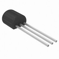
IC TEMP SENSOR 3.3V TO92-3 STR
Manufacturer
Analog Devices Inc
Datasheet
1.AD22103KTZ.pdf
(6 pages)
Specifications of AD22103KTZ
Sensing Temperature
0°C ~ 100°C
Output Type
Voltage
Voltage - Supply
2.7 V ~ 3.6 V
Accuracy
±0.5°C
Package / Case
TO-226-3, TO-92-3 (TO-226AA)
Ic Output Type
Voltage
Sensing Accuracy Range
± 0.5°C
Supply Current
500µA
Supply Voltage Range
2.7V To 3.6V
Resolution (bits)
8bit
Sensor Case Style
TO-92
No. Of Pins
3
Temperature Sensor Function
Temp Sensor
Package Type
TO-92
Operating Temperature (min)
0C
Operating Temperature (max)
100C
Operating Temperature Classification
Commercial
Operating Supply Voltage (min)
2.7V
Operating Supply Voltage (typ)
3.3V
Operating Supply Voltage (max)
3.6V
Rohs Compliant
Yes
Lead Free Status / RoHS Status
Lead free / RoHS Compliant
Lead Free Status / RoHS Status
Lead free / RoHS Compliant, Lead free / RoHS Compliant


AD22103
THEORY OF OPERATION
The AD22103 is a ratiometric temperature sensor IC whose
output voltage is proportional to power supply voltage. The
heart of the sensor is a proprietary temperature-dependent resis-
tor, similar to an RTD, which is built into the IC. Figure 4
shows a simplified block diagram of the AD22103.
The temperature-dependent resistor, labeled R
change in resistance that is nearly linearly proportional to tem-
perature. This resistor is excited with a current source that is
proportional to power supply voltage. The resulting voltage
across R
early varying with temperature. The remainder of the AD22103
consists of an op amp signal conditioning block that takes the
voltage across R
achieve the following output voltage function:
ABSOLUTE ACCURACY AND NONLINEARITY
SPECIFICATIONS
Figure 5 graphically depicts the guaranteed limits of accuracy
for the AD22103 and shows the performance of a typical part.
As the output is very linear, the major sources of error are offset,
i.e., error at room temperature, and span error, i.e., deviation
from the theoretical 28.0 mV/ C. Demanding applications can
achieve improved performance by calibrating these offset and
gain errors so that only the residual nonlinearity remains as a
source of error.
V
OUT
–0.5
–1.0
–1.5
–2.0
–2.5
T
2.5
2.0
1.5
1.0
0.5
Figure 5. Typical AD22103 Performance
is therefore both supply voltage proportional and lin-
0
0
Figure 4. Simplified Block Diagram
= (V
R
T
T
S
and applies the proper gain and offset to
/3.3 V)
+V
S
TEMPERATURE – C
[0.25 V + (28.0 mV/ C)
50
V
V
V
S
S
S
= 2.7V
= 3.6V
= 3.3V
T
, exhibits a
T
V
A
100
OUT
]
–4–
OUTPUT STAGE CONSIDERATIONS
As previously stated, the AD22103 is a voltage output device. A
basic understanding of the nature of its output stage is useful for
proper application. Note that at the nominal supply voltage of
3.3 V, the output voltage extends from 0.25 V at 0 C to +3.05 V
at +100 C. Furthermore, the AD22103 output pin is capable of
withstanding an indefinite short circuit to either ground or the
power supply. These characteristics are provided by the output
stage structure shown in Figure 6.
The active portion of the output stage is a PNP transistor with
its emitter connected to the V
to the output node. This PNP transistor sources the required
amount of output current. A limited pull-down capability is
provided by a fixed current sink of about –100 A. (Here,
“fixed” means the current sink is fairly insensitive to either sup-
ply voltage or output loading conditions. The current sink ca-
pability is a function of temperature, increasing its pull-down
capability at lower temperatures.)
Due to its limited current sinking ability, the AD22103 is inca-
pable of driving loads to the V
tended to drive grounded loads. A typical value for short circuit
current limit is 7 mA, so devices can reliably source 1 mA or
2 mA. However, for best output voltage accuracy and minimal
internal self-heating, output current should be kept below 1 mA.
Loads connected to the V
the current sinking capability of the AD22103 is very limited.
These considerations are typically not a problem when driving
a microcontroller analog to digital converter input pin (see
MICROPROCESSOR A/D INTERFACE ISSUES).
MOUNTING CONSIDERATIONS
If the AD22103 is thermally attached and properly protected, it
can be used in any measuring situation where the maximum
range of temperatures encountered is between 0 C and +100 C.
Because plastic IC packaging technology is employed, excessive
mechanical stress must be avoided when fastening the device
with a clamp or screw-on heat tab. Thermally conductive epoxy
or glue is recommended for typical mounting conditions. In wet
or corrosive environments, an electrically isolated metal or ce-
ramic well should be used to shield the AD22103. Because the
part has a voltage output (as opposed to current), it offers mod-
est immunity to leakage errors, such as those caused by conden-
sation at low temperatures.
Figure 6. Output Stage Structure
V
S
S
power supply should be avoided as
S
S
supply and collector connected
power supply and is instead in-
V
OUT
REV. 0
Related parts for AD22103KTZ
Image
Part Number
Description
Manufacturer
Datasheet
Request
R

Part Number:
Description:
±1.7g Dual-Axis IMEMS Accelerometer Evaluation Board
Manufacturer:
Analog Devices Inc
Datasheet:

Part Number:
Description:
Inertial Sensor Evaluation System
Manufacturer:
Analog Devices Inc
Datasheet:
Part Number:
Description:
Manufacturer:
Analog Devices Inc
Datasheet:
Part Number:
Description:
Manufacturer:
Analog Devices Inc
Datasheet:
Part Number:
Description:
Manufacturer:
Analog Devices Inc
Datasheet:
Part Number:
Description:
Manufacturer:
Analog Devices Inc
Datasheet:
Part Number:
Description:
Manufacturer:
Analog Devices Inc
Datasheet:
Part Number:
Description:
Manufacturer:
Analog Devices Inc
Datasheet:
Part Number:
Description:
Manufacturer:
Analog Devices Inc
Datasheet:
Part Number:
Description:
Manufacturer:
Analog Devices Inc
Datasheet:
Part Number:
Description:
Manufacturer:
Analog Devices Inc
Datasheet:
Part Number:
Description:
Manufacturer:
Analog Devices Inc
Datasheet:
Part Number:
Description:
Manufacturer:
Analog Devices Inc
Datasheet: