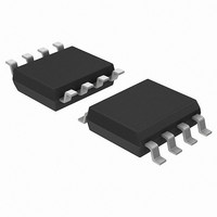
DS1720S Maxim Integrated Products, DS1720S Datasheet

DS1720S
Specifications of DS1720S
Available stocks
Related parts for DS1720S
DS1720S Summary of contents
Page 1
... ECON-Digital Thermometer and PIN ASSIGNMENT CLK/CONV 2 7 RST GND DS1720S 8-Pin SOIC (208-mil) PIN DESCRIPTION DQ – 3–Wire Input/Output CLK/ – 3–Wire Clock Input and CONV Stand–alone Convert Input – 3–Wire Reset Input RST GND – Ground T – High Temperature Trigger ...
Page 2
... DS1720 (see note) DS1720S+T&R DS1720 (see note) DS1720S DS1720 DS1720S/T&R DS1720 Note: A “+” symbol will also be marked on the package near the Pin 1 indicator. OPERATION–MEASURING TEMPERATURE A block diagram of the DS1720 is shown in Figure 1. The DS1720 measures temperatures through the use of an on–board proprietary temperature measurement technique. A block diagram of the temperature measurement circuitry is shown in Figure 2 ...
Page 3
DS1720 FUNCTIONAL BLOCK DIAGRAM Figure DS1720 ...
Page 4
... Since data is transmitted over the 3–wire bus LSB first, temperature data can be written to/read from the DS1720 as either a 9–bit word (taking words, with the most significant 7 bits being ignored or set to zero, as illustrated in Table 1. After the MSB, the DS1720 will output 0s. ...
Page 5
... OPERATION–THERMOSTAT CONTROLS Three thermally triggered outputs thermostat, as shown in Figure 3. When the DS1720’s temperature meets or exceeds the value stored in the high temperature trip register, the output T DS1720’s measured temperature becomes less than the stored value in the high temperature register, TH. ...
Page 6
... This feature provides a method of determining if the DS1720 has ever been subjected to temperatures above T while power has been applied Temperature Low Flag. This bit will be set to 1 when the temperature is less than or equal to the LF value will remain 1 until reset by writing 0 into this location or by removing power from the L device ...
Page 7
... T output. HIGH Write T [02h] L This command writes to the T L nine clock cycles clock in the 9–bit temperature limit which will set the threshold for operation of the T output. LOW , will remain in the state they were in after the HIGH LOW ...
Page 8
... Read T [A1h] H This command reads the value of the T the next nine clock cycles clock out the 9–bit temperature limit which sets the threshold for operation of the T output. HIGH Read T [A2h] L This command reads the value of the T the next nine clock cycles clock out the 9–bit temperature limit which sets the threshold for operation of the T output ...
Page 9
... Start Convert T command must be issued. In one–shot mode, a Start Convert T command must be issued for every temperature reading desired Writing to the E typically requires room temperature. After issuing a write command, no further writes should be requested for at least 10 ms. PROTOCOL THERMOSTAT COMMANDS register ...
Page 10
FUNCTION EXAMPLE Example: CPU sets up DS1720 for continuous conversion and thermostatic function. DS1720 MODE CPU MODE (3-WIRE ...
Page 11
READ DATA TRANSFER Figure 4 WRITE DATA TRANSFER Figure DS1720 ...
Page 12
... Voltage on Any Pin Relative to Ground Operating Temperature Storage Temperature Soldering Temperature *This is a stress rating only and functional operation of the device at these or any other conditions above those indicated in the operation sections of this specification is not implied. Exposure to absolute maximum rating conditions for extended periods of time may affect reliability. ...
Page 13
... AC ELECTRICAL CHARACTERISTICS PARAMETER SYMBOL Temperature Conversion Time Data to CLK Setup CLK to Data Hold CLK to Data Delay CLK Low Time CLK High Time CLK Frequency CLK Rise and Fall to CLK Setup RST CLK to Hold RST Inactive Time RST CLK High to I/O High-Z ...
Page 14
DS1720 TYPICAL THERMOMETER ERROR DS1720 DS1720 ...


