NTCLE203E3104GB0 Vishay, NTCLE203E3104GB0 Datasheet - Page 14
NTCLE203E3104GB0
Manufacturer Part Number
NTCLE203E3104GB0
Description
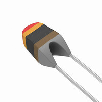
THERMISTOR NTC 100K 2% RADIAL
Manufacturer
Vishay
Series
2381r
Type
NTCr
Datasheets
1.NTCLE100E3472JB0.pdf
(17 pages)
2.NTCLE203E3103GB0.pdf
(9 pages)
3.NTCLE203E3104GB0.pdf
(17 pages)
Specifications of NTCLE203E3104GB0
Resistance In Ohms @ 25°c
100K
Resistance Tolerance
±2%
B Value Tolerance
±1.5%
B25/85
4190K
Operating Temperature
-40°C ~ 150°C
Power - Max
100mW
Lead Length
1.58" (40.00mm)
Mounting Type
Through Hole
Package / Case
Radial - Molded Bead
Mounting Style
Through Hole
Pin Count
2
Screening Level
Automotive
Sensitivity Index
4190K
Resistance @ 25c
100kohm
Thermal Time Constant
15s
Percentage Of Resistance Tolerance @ 25c
±2
Accuracy
±1.5
Operating Temperature Min Deg. C
-40C
Operating Temperature Max Deg. C
125C
Product Length (mm)
3.3mm
Product Height (mm)
9mm
Product Depth (mm)
3mm
Lead Free Status / RoHS Status
Lead free / RoHS Compliant
B0/50
-
B25/50
-
B25/75
-
B25/100
-
Lead Free Status / Rohs Status
Lead free / RoHS Compliant
Other names
2381 640 54104
2381 640 54104
238164054104
BC2529
2381 640 54104
238164054104
BC2529


NTCLE100E3
Vishay BCcomponents
PACKAGING
TAPE SPECIFICATIONS
www.vishay.com
70
1E pitch
NTCLE100E3...T1
Thermistors on tape
DIMENSIONS in millimeters
DETAILS
Body diameter
Lead diameter
Feed hole diameter
Lead to lead distance
Distance component to tape centre
Component height
Component alignment
Distance top/bottom of components
Length of lacquer under the comp. bottom
Length of snipped lead
Pitch between thermistors
Feed hole pitch
Feed hole center to lead center
Component alignment
Total thickness
Total tape thickness
Tape width
Hold down tape width
Hole position
Hold down tape position
L
H
3
Direction of unreeling
D
P
0
NTC Thermistors, Radial Leaded,
For technical questions, contact:
SYMBOL DIMENSIONS NOMINAL TOLERANCE
d
p
W
W
W
D
H
h
H
H
P
P
W
D
H
P
d
F
L
T
t
0
1
0
1
2
3
P
D
0
1
2
0
P
Standard Precision
1
F
detail A
P
2.54
22.0
32.2
11.0
12.7
12.7
5.08
18.0
3.0
0.9
3.3
0.6
4.0
5.0
9.0
1.5
0
6
2
0
t
nlr@vishay.com
W
W
0
2
W
1
± 0.3
± 0.5
± 0.2
± 1.0
max.
± 2.0
max.
± 1.0
± 0.3
± 0.7
± 1.3
max.
max.
± 1.0
± 0.3
± 0.5
± 1.0
± 10
- 0.5
max.
± 1
W
H
H
2
Taped according to IEC 60286-2
(cover tape may differ from shown)
H
1
5 max. for 3.3 to 220
Guaranteed between
component and tape
1 to 4 max. for 3.3 to 220
Cumulative pitch error
± 1 mm/20 pitches
guaranteed between
component and tape
4 max. for 3.3 to 220 with
cardboard tape 0.5 ± 0.1
None of the hold down tapes may
cover the holes
H
Document Number: 29049
REMARKS
T
Revision: 12-Apr-11
A
Related parts for NTCLE203E3104GB0
Image
Part Number
Description
Manufacturer
Datasheet
Request
R

Part Number:
Description:
357-036-542-201 CARDEDGE 36POS DL .156 BLK LOPRO
Manufacturer:
Vishay
Datasheet:
Part Number:
Description:
357-036-542-201 CARDEDGE 36POS DL .156 BLK LOPRO
Manufacturer:
Vishay
Datasheet:
Part Number:
Description:
357-036-542-201 CARDEDGE 36POS DL .156 BLK LOPRO
Manufacturer:
Vishay
Datasheet:
Part Number:
Description:
357-036-542-201 CARDEDGE 36POS DL .156 BLK LOPRO
Manufacturer:
Vishay
Datasheet:
Part Number:
Description:
357-036-542-201 CARDEDGE 36POS DL .156 BLK LOPRO
Manufacturer:
Vishay
Datasheet:
Part Number:
Description:
357-036-542-201 CARDEDGE 36POS DL .156 BLK LOPRO
Manufacturer:
Vishay
Datasheet:
Part Number:
Description:
357-036-542-201 CARDEDGE 36POS DL .156 BLK LOPRO
Manufacturer:
Vishay
Datasheet:
Part Number:
Description:
357-036-542-201 CARDEDGE 36POS DL .156 BLK LOPRO
Manufacturer:
Vishay
Datasheet:
Part Number:
Description:
357-036-542-201 CARDEDGE 36POS DL .156 BLK LOPRO
Manufacturer:
Vishay
Datasheet:
Part Number:
Description:
357-036-542-201 CARDEDGE 36POS DL .156 BLK LOPRO
Manufacturer:
Vishay
Datasheet:
Part Number:
Description:
357-036-542-201 CARDEDGE 36POS DL .156 BLK LOPRO
Manufacturer:
Vishay
Datasheet:
Part Number:
Description:
357-036-542-201 CARDEDGE 36POS DL .156 BLK LOPRO
Manufacturer:
Vishay
Datasheet:
Part Number:
Description:
357-036-542-201 CARDEDGE 36POS DL .156 BLK LOPRO
Manufacturer:
Vishay
Datasheet:
Part Number:
Description:
357-036-542-201 CARDEDGE 36POS DL .156 BLK LOPRO
Manufacturer:
Vishay
Datasheet:
Part Number:
Description:
357-036-542-201 CARDEDGE 36POS DL .156 BLK LOPRO
Manufacturer:
Vishay
Datasheet: