B57411V2331J62 EPCOS Inc, B57411V2331J62 Datasheet - Page 15
B57411V2331J62
Manufacturer Part Number
B57411V2331J62
Description
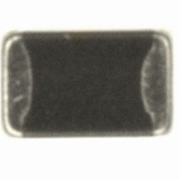
THERMISTOR NTC 330 OHM 5% 0805
Manufacturer
EPCOS Inc
Series
B574**V2r
Type
NTCr
Specifications of B57411V2331J62
Package / Case
0805 (2012 Metric)
Resistance In Ohms @ 25°c
330
Resistance Tolerance
±5%
B Value Tolerance
±3%
B25/50
3500K
B25/85
3540K
B25/100
3550K
Operating Temperature
-55°C ~ 125°C
Power - Max
210mW
Mounting Type
Surface Mount
Resistance
330 Ohms
Tolerance
5 %
Termination Style
SMD/SMT
Operating Temperature Range
- 55 C to + 125 C
Dimensions
1.25 mm W x 2 mm L x 1.3 mm H
Power Rating
210 mW
Lead Free Status / RoHS Status
Lead free / RoHS Compliant
B0/50
-
B25/75
-
Lead Length
-
Lead Free Status / Rohs Status
Lead free / RoHS Compliant
Other names
495-3075-2
B57411V2331J 62
B57411V2331J062
B57411V2331J62
B57411V2331J 62
B57411V2331J062
B57411V2331J62


6
a) Component placement
b) Cracks
c) Component orientation
Please read Cautions and warnings and
Important notes at the end of this document.
Temperature measurement and compensation
SMD NTC thermistors, case size 0805 (2012)
Placement and orientation of SMD NTC thermistors on PCB
Page 15 of 20
It is recommended that the PC board
should be held by means of some
adequate supporting pins such as
shown left to prevent the SMDs from
being damaged or cracked.
When placing a component near an
area which is apt to bend or a grid
groove on the PC board, it is advisable
to have both electrodes subjected to
uniform stress, or to position the
component's electrodes at right angles
to the grid groove or bending line (see
c) Component orientation).
Choose a mounting position that
minimizes the stress imposed on the
chip during flexing or bending of the
board.
B574**V2
Related parts for B57411V2331J62
Image
Part Number
Description
Manufacturer
Datasheet
Request
R

Part Number:
Description:
Temperature Measurement SMD NTC Thermistors with Nickel Barrier Termination
Manufacturer:
Epcos
Datasheet:


Part Number:
Description:
CAP .15UF 63V METAL POLY
Manufacturer:
EPCOS Inc
Datasheet:


Part Number:
Description:
CAP .01UF 400V METAL POLY
Manufacturer:
EPCOS Inc
Datasheet:
