XA1E-LV313Q4V-R IDEC, XA1E-LV313Q4V-R Datasheet - Page 6
XA1E-LV313Q4V-R
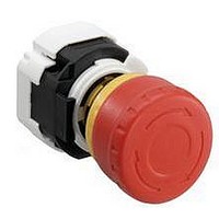
Manufacturer Part Number
XA1E-LV313Q4V-R
Description
SWITCH, EMERGENCY STOP, 1NO/3NC, 250VAC
Manufacturer
IDEC
Datasheet
1.XA1E-BV311-R.pdf
(6 pages)
Specifications of XA1E-LV313Q4V-R
Contact Configuration
4PST-3NC / 1NO
Switch Operation
Pushlock Reset/Push-Pull
Contact Voltage Ac Nom
250V
Contact Voltage Dc Nom
250V
Contact Current Max
3A
Illumination Color
Red
Lead Free Status / RoHS Status
Lead free / RoHS Compliant


456
Wiring
1. The applicable wire size is 16 AWG maximum.
2. Solder the terminal at a temperature of 310 to 350°C within 3 seconds using
3. Use a non-corrosive rosin fl ux.
4. Because the terminal spacing is narrow, use protective tubes or heat shrink-
PC Board Terminal Type
1. When mounting a contact block on a PC board, provide suffi cient rotating
2. When mounting an XA emergency stop switch on a PC board, make sure that
About PC Board and Circuit Design
1. Use PC boards made of glass epoxy copper-clad laminated sheets of 1.6 mm
2. PC boards and circuits must withstand rated voltage and current, including
3. The minimum applicable load is 5V AC/DC, 1 mA.
4. Within the 2.8* mm areas shown in the fi gure below, terminals touch the PC
Safety Precautions
a soldering iron. Sn-Ag-Cu solder is recommended. When soldering, do not
touch the switch with the soldering iron. Also ensure that no tensile force is
applied to the terminals. Do not bend the terminals or apply excessive force to
the terminals.
able tubes to avoid burning of wire coating or short circuit.
space for the PC board when installing and removing the contact block.
the operator is securely installed.
in thickness, with double-sided through holes.
instantaneous current and voltage at switching.
board, resulting in possible short circuit on the printed circuit. When design-
ing a PC board pattern, take this possibility into consideration.
Surface for installing
components
•
•
Solder Surface
Turn off power to the XA series emergency stop switch before starting
installation, removal, wiring, maintenance, and inspection of the relays.
Failure to turn power off may cause electrical shock or fi re hazard.
Use the LED unit removal tool when replacing the LED unit to avoid burning
your hands.
(0.5)
16mm XA E-Stops
2.8∗
19.8
8.7
Solder Surface
(0.5)
2.8∗
Operating Instructions, continued
1.6 (PC Board)
Surface for installing
components
All dimensions in mm.
www.idec.com
Installing Insulation Terminal Cover
To install the terminal cover (XA9Z-VL2), align the TOP marking on the terminal
cover with TOP marking on the contact block, and press the terminal cover
toward the contact block.
Note: For wiring, insert the wires into the holes in the terminal cover before soldering.
Contact Bounce
When the button is reset by pulling or turning, the NC main contacts will bounce.
When pressing the button, the NO monitor contacts will bounce.
When designing a control circuit, take the contact bounce time into consider-
ation (reference value: 20 ms).
Nameplate
When anti-rotation is not required, remove the projection from the nameplate
using pliers.
Handling
Do not expose the switch to excessive shock and vibration, otherwise the switch
may be deformed or damaged, causing malfunction or operation failure.
•
Use wires of the proper size to meet the voltage and current requirements,
and solder the wires correctly. If soldering is incomplete, the wire may heat
during operation, causing a fi re hazard.
Switches & Pilot Devices
Projection
Nameplate
Related parts for XA1E-LV313Q4V-R
Image
Part Number
Description
Manufacturer
Datasheet
Request
R

Part Number:
Description:
Cable; Between IDEC MicroSmart (port 1 or 2) and HG2F/3F/4F; 5 ft.
Manufacturer:
IDEC Corporation
Datasheet:
Part Number:
Description:
Cable; Between IDEC Micro^3C/ONC/MicroSmart (port 2) PLCs and HG2F/3F/4F; 5 ft.
Manufacturer:
IDEC Corporation
Datasheet:
Part Number:
Description:
Angled Key for Idec HS6B Safety Switch
Manufacturer:
IDEC Corporation
Datasheet:
Part Number:
Description:
Accessory, L-Shaped Key for Idec HS5B and HS5E Safety Switch
Manufacturer:
IDEC Corporation
Datasheet:
Part Number:
Description:
Accessory, Straight Key for Idec HS5B and HS5E Safety Switch
Manufacturer:
IDEC Corporation
Datasheet:
Part Number:
Description:
Straight Key for Idec HS6B Safety Switch
Manufacturer:
IDEC Corporation
Datasheet:
Part Number:
Description:
LIGHT TOWER 3 TIER RED/AMBER/GREEN 24VAC/DC WALL MOUNT
Manufacturer:
IDEC Corporation
Datasheet:
Part Number:
Description:
Flat Lens, 24V AC/DC, 1m Cable Length, Alternate: Red Green Color, IP67
Manufacturer:
IDEC Corporation
Datasheet:
Part Number:
Description:
LIGHT TOWER 2 TIER RED/GREEN 24VAC/DC WALL MOUNT
Manufacturer:
IDEC Corporation
Datasheet:
Part Number:
Description:
LIGHT TOWER 2 TIER RED/GREEN 24VAC/DC DIRECT MOUNT
Manufacturer:
IDEC Corporation
Datasheet:
Part Number:
Description:
INDICATOR INCANDESCENT LAMP, GREEN
Manufacturer:
IDEC
Datasheet:

Part Number:
Description:
LAMP, INDICATOR, INCAND, AMB
Manufacturer:
IDEC
Datasheet:
Part Number:
Description:
LAMP, INDICATOR, INCAND, GRN
Manufacturer:
IDEC
Datasheet:
Part Number:
Description:
LAMP, INDICATOR, INCAND, GRN
Manufacturer:
IDEC
Datasheet:
Part Number:
Description:
LAMP, INDICATOR, INCANDESCENT, RED
Manufacturer:
IDEC
Datasheet: