HW1S-5TF22N3 IDEC, HW1S-5TF22N3 Datasheet - Page 60
HW1S-5TF22N3
Manufacturer Part Number
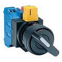
HW1S-5TF22N3
Description
SWITCH, SELECTOR, SPST, 10A, 600V
Manufacturer
IDEC
Series
HWr
Datasheet
1.HW1A-B1-R.pdf
(61 pages)
Specifications of HW1S-5TF22N3
No. Of Poles
4
No. Of Switch Positions
5
Contact Current Ac Max
10A
Contact Current Dc Max
8A
Contact Voltage Ac Max
600V
Contact Voltage Dc Max
220V
Circuitry
SPST
Lead Free Status / RoHS Status
Lead free / RoHS Compliant


Oiltight Switches & Pilot Devices
Turn off power to HW series control units before starting installation, removal,
wiring, maintenance, and inspection of the products. Failure to turn power off
may cause electrical shocks or fire hazard.
To avoid the possibility of burning yourself, use the lamp holder tool when
replacing lamps.
Panel Mounting
Remove the contact block assembly from the operator (for transformer type pilot
lights, remove the transformer from the illumination unit). Remove the locking
ring from the operator. Insert the operator into the panel cut-out from the front,
tighten the locking ring from the back, then install the contact block assembly to
the operator.
Removing and Installing the Contact Block Assembly
1. To remove the operator from the contact block, turn the locking lever in the
2. To reinstall, place the TOP markings on the operator and the contact block
Notes for Panel Mounting
1. When mounting the operator onto a panel, use the optional locking ring
2. For the contact blocks and transformers housing LED and incandescent lamps,
Replacement of Lens
Removing
Remove the lens by inserting a screwdriver into the recess of the lens through
the bezel.
Installing
Install the lens in the recess between the buttons by pressing against the bezel.
direction of the arrow shown below. The operator can now be removed.
mounting adapter in the same direction, and insert the operator into the
contact block mounting adapter. Then turn the locking lever in the opposite
direction.
wrench (MW9Z-T1) to tighten the locking ring. Tightening torque must not
exceed 2.0 N·m. Do not use pliers. Excessive tightening will damage the
locking ring.
make sure not to press the lamps too hard, otherwise the lamp socket may be
damaged.
USA: 800-262-IDEC
Dual Pushbutton Instructions
HW General Instructions
HW Safety Precautions
Canada: 888-317-IDEC
For wiring, use wires of a proper size to meet voltage and current requirements.
Tighten the M3.5 terminal screws to a tightening torque of 1.0 to 1.3 N·m.
Failure to tighten terminal screws may cause overheating and fire.
Safety Lever Lock
IDEC strongly recommends using the safety lever lock (HW9Z-LS, yellow) to
prevent heavy vibration or maintenance personnel from unlocking the contact
assembly.
1. HW series can be mounted vertically with a minimum spacing of 55 mm
2. Mount the control unit onto the panel, lock the lever, and push in the safety
3. When the spacing is narrower than the recommended value, with the lever un-
4. To remove the safety lever lock, insert a flat screwdriver into the safety lever
but spacing should be determined to ensure easy operation (recommended
minimum spacing: 100 mm).
lever lock to install.
locked, mount the safety lever lock and insert the contact unit to the operator.
Then, lock the lever and strongly push in the safety lever lock to install.
and push upwards.
Screwdriver
Contact Block
Mounting Adapter
Safety Lever Lock
ø22mm - HW Series
Remove
Panel
Operator
Lock Lever
Safety Lever
Lock
559
Related parts for HW1S-5TF22N3
Image
Part Number
Description
Manufacturer
Datasheet
Request
R

Part Number:
Description:
HW1S-4TF22N3 4POS MNTD SEL SW
Manufacturer:
IDEC
Datasheet:
Part Number:
Description:
HW1S-31TF20 3POS SPRNG SEL SW
Manufacturer:
IDEC
Datasheet:
Part Number:
Description:
HW1S-32TF20 3POS SPRNG SEL SW
Manufacturer:
IDEC
Datasheet:
Part Number:
Description:
HW1S-33LF20 3Pos Sprg-Bth Slctr SW
Manufacturer:
IDEC
Datasheet:
Part Number:
Description:
HW1S-33TF20 3POS SPRNG SEL SW
Manufacturer:
IDEC
Datasheet:
Part Number:
Description:
HW1S-33TF22 HW 3POS SPRNG SEL SW
Manufacturer:
IDEC
Datasheet:
Part Number:
Description:
HW1S-3LF20 3Pos Mtd Slctr SW
Manufacturer:
IDEC
Datasheet:

Part Number:
Description:
HW1S-3TF11 3 Pos Mtd Selector Switch 1NO/1NC
Manufacturer:
IDEC
Datasheet:
Part Number:
Description:
HW1S-3TF40 HW 3POS MNTD SEL SW
Manufacturer:
IDEC
Datasheet:
Part Number:
Description:
HW1S-2T22 HW 2POS MNTD SEL SW G-Cntcts
Manufacturer:
IDEC
Datasheet:

Part Number:
Description:
INDICATOR INCANDESCENT LAMP, GREEN
Manufacturer:
IDEC
Datasheet:

Part Number:
Description:
LAMP, INDICATOR, INCAND, AMB
Manufacturer:
IDEC
Datasheet:
Part Number:
Description:
LAMP, INDICATOR, INCAND, GRN
Manufacturer:
IDEC
Datasheet:
Part Number:
Description:
LAMP, INDICATOR, INCAND, GRN
Manufacturer:
IDEC
Datasheet: