A7B-M-1 Omron, A7B-M-1 Datasheet - Page 7
A7B-M-1
Manufacturer Part Number
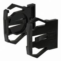
A7B-M-1
Description
Endcap, Ship 1 LFT And 1 RGT
Manufacturer
Omron
Series
A7Br
Type
Thumbwheel Switchr
Specifications of A7B-M-1
Accessory Type
End Cap
Application
Reliable Thumbwheel with Easy-to-Mount Assembly
Features
Dustproof construction ensures highly reliable performance at low voltage and very small
Height
24 mm
Length
5.5 mm
Width
0.94 mm
Color
Black
Lead Free Status / RoHS Status
Lead free / RoHS Compliant
For Use With/related Products
SW266 ~ SW269
For Use With
SW266 - SWITCH THUMBWHEEL BLACK BCDSW267 - SWITCH THUMBWHEEL BLACK BCDSW268 - SWITCH THUMBWHEEL EXT BRD BCDSW269 - SWITCH THUMBWHEEL EXT BRD +,-DIS
Lead Free Status / Rohs Status
Lead free / RoHS Compliant
Other names
A7BM1
SW271
SW271


Ordering Procedure
Place orders as shown in the example below, specifying the model
and number. Standard products are not factory-assembled for
shipment. Contact your OMRON representative for details on
ordering factory-assembled sets.
1. A7BS-206 (Switch Unit): 2 pieces
2. A7BS-207 (Switch Unit): 2 pieces
3. A7B-PA (Spacer): 1 piece
4. A7B-M (End Caps): 1 pair
Safety Precautions
Refer to Precautions for Correct Use on page
Handling
Setting Numbers
Locking Type
• The molded components of the Switch use polyacetal resin and
• A7BS/A7BL Thumbwheel Switches are not drip-proof. Do not use
• Do not allow solder flux or alcohol to enter the Switch.
• Set with the setting button by raising it.
• Return the button to its original position after setting. It is then
ABS resin. It is recommended that alcohol is used to wipe off dirt
and smudges from the molded components. Take care to prevent
the alcohol from getting inside.
them in areas subject to water or oil.
locked to prevent rotation, and the set numbers will not change
accidentally.
Precautions for Correct Use
4
1
3
2
4
in the
Technical Guide for Thumbwheel Switches
Models with External Stoppers (A7BS-20@-S)
With the A7BS-20@-S, any range can be set externally using the
Stopper Pin. Insert the Stopper Pin using the following procedure:
1. Any number within the range of (0 to 7) can be chosen to limit the
2. First, insert the Stopper Pin in the hole
3. Next, inset the Stopper Pin in the hole
4. Confirm that the (+) push-button can no
5. Confirm that the (-) push-button can no longer be pushed after
numbers displayed in the display window. (In this example, 8 and
9 are outside of this range.)
in front of the lower limit (“0”) for the
number to be defined.
past the upper limit (“7”) for the number
to be defined. (The Stopper Pins then
surround the exact range to be
defined.)
longer be pushed after reaching the
upper limit of (“7”).
reaching the lower limit of (“0”). This completes the setting.
Example: To Display the Range 0 to 7
(3) Stopper Pin (upper limit)
(2) Stopper Pin (lower limit)
A7BS/A7BL
(1) Display window
.
7
Related parts for A7B-M-1
Image
Part Number
Description
Manufacturer
Datasheet
Request
R

Part Number:
Description:
Endcap, Ship 1 LFT And 1 RGT
Manufacturer:
Omron
Datasheet:


Part Number:
Description:
SPACER W/DECIMAL POINT
Manufacturer:
Omron
Datasheet:

Part Number:
Description:
G6S-2GLow Signal Relay
Manufacturer:
Omron Corporation
Datasheet:
Part Number:
Description:
Compact, Low-cost, SSR Switching 5 to 20 A
Manufacturer:
Omron Corporation
Datasheet:
Part Number:
Description:
Manufacturer:
Omron Corporation
Datasheet:
Part Number:
Description:
Manufacturer:
Omron Corporation
Datasheet: