D3M-01K1 Omron, D3M-01K1 Datasheet - Page 2
D3M-01K1
Manufacturer Part Number
D3M-01K1
Description
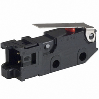
Switches, Microswitch Switch Type:Snap-Acting Basic Switch
Manufacturer
Omron
Series
D3Mr
Type
Sub-Miniature Snap-Action Switchesr
Datasheet
1.D3M-01L2-3.pdf
(6 pages)
Specifications of D3M-01K1
Circuit
SPST-NC
Switch Function
On-Mom
Contact Rating @ Voltage
0.1A @ 30VDC
Actuator Type
Lever, Straight
Mounting Type
Chassis Mount
Termination Style
Connector
Operating Force
51gf
Contact Form
SPST - NC
Contact Rating
0.1 Amp
Actuator
Lever
Lead Free Status / RoHS Status
Lead free / RoHS Compliant
Lead Free Status / RoHS Status
Lead free / RoHS Compliant, Lead free / RoHS Compliant
Other names
D3M01K1
SW879
SW879


Specifications
■ Characteristics
Note: 1. Data shown are of initial value.
■ Approved Standards
UL Recognized/CSA Certified
EN61058-1 (TÜV Rheinland approval)
Testing conditions: 1E5 (100,000 operations), T85 (0°C to 85°C)
Engineering Data
■ Mounting Holes
All switches may be panel mounted using M2.3 mounting screws with
plane washers or spring washers to securely mount the switch.
Tighten the screws to a torque of 0.23 to 0.26 N·m.
58
Electrical Rating (See note 4)
Operating speed
Operating frequency
Insulation resistance
Contact resistance
Dielectric strength (See note 2)
Vibration resistance (See note 3)
Shock resistance (See note 3)
Degree of protection
Degree of protection against electric shock Class I
Proof tracking index (PTI)
Ambient operating temperature
Ambient operating humidity
Life expectancy
Weight
30 VDC
30 VDC
2. The dielectric strength shown is measured using a separator between the switch and metal mounting plate.
3. For the pin plunger models, the above values apply for use at the free position and total travel position. For the lever models, they apply
4.
Rated voltage
Rated voltage
at the total travel position. Contact opening or closing time is within 1 ms.
The electrical ratings apply under the following test conditions: Ambient Temperature = 20
erations/min.
Subminiature Snap Action Switch
Two, 2.4-dia. mounting hole or M2.3 screw hole
9.5
±0.1
0.1 A
0.1 A
D3M
D3M
0.1 A at 30 VDC, resistive
0.1 mm/s to 1 m/s (pin plunger models)
Mechanical: 400 operations/minute max.
Electrical: 30 operations/minute max.
100 MΩ min. at 500 VDC
100 mΩ max. including connector and 50-mm AWG28 lead wire resistance
1,000 VAC at 50/60 Hz for 1 minute between terminals of the same polarity
1,500 VAC at 50/60 Hz for 1 minute between charged metal part and ground
1,500 VAC at 50/60 Hz for 1 minute between non-charged metal part and each terminal
Malfunction: 10 to 55 Hz, 1.5-mm double amplitude
Destruction: 1,000 m/s
Malfunction: 300 m/s
175
-25°C to 85°C (at 60% RH max) with no icing
85% max. (for 5°C to 35°C)
Mechanical: 500,000 operations at 60 operations/minute
Electrical: 200,000 operations at 30 operations/minute
Approx. 2 g (pin plunger model)
IEC IP40
D3M
2
(approx. 30G) max.
2
(approx. 100G) max.
■ Contact Specifications
Note: Minimum applicable loads are indicated by N standard refer-
■ Contact Form
Specification
Material
Contact gap
Inrush current
Minimum applicable load
(see note)
ence values. This value represents the failure rate at a 60%
(λ
The equation
rate of 1/2,000,000 operations can be expected at a reliability
level of 60%
SPST-NC
60
) reliability level (JIS C5003).
±
2
°
Item
C, Ambient Humidity = 65
λ
60
=0.5 x 10
-6
Crossbar
Gold alloy
0.5 mm
1 A max.
1 mA at 5 VDC
/ operations indicates that a failure
±
5%, Operating frequency = 30 op-
SPST-NO
Specification
Related parts for D3M-01K1
Image
Part Number
Description
Manufacturer
Datasheet
Request
R

Part Number:
Description:
Switches, Microswitch Switch Type:Snap-Acting Basic Switch
Manufacturer:
Omron
Datasheet:

Part Number:
Description:
Switches, Microswitch Switch Type:Snap-Acting Basic Switch
Manufacturer:
Omron
Datasheet:

Part Number:
Description:
MINIATURE BASIC SWITCH
Manufacturer:
Omron
Datasheet:

Part Number:
Description:
Switches, Microswitch Switch Type:Snap-Acting Basic Switch
Manufacturer:
Omron
Datasheet:

Part Number:
Description:
Switches, Microswitch Switch Type:Snap-Acting Basic Switch
Manufacturer:
Omron
Datasheet:

Part Number:
Description:
Switches, Microswitch Switch Type:Snap-Acting Basic Switch
Manufacturer:
Omron
Datasheet:

Part Number:
Description:
Switches, Microswitch Switch Type:Snap-Acting Basic Switch
Manufacturer:
Omron
Datasheet:

Part Number:
Description:
Switches, Microswitch Switch Type:Snap-Acting Basic Switch
Manufacturer:
Omron
Datasheet:

Part Number:
Description:
Switches, Microswitch Switch Type:Snap-Acting Basic Switch
Manufacturer:
Omron
Datasheet:

Part Number:
Description:
Switches, Microswitch Switch Type:Snap-Acting Basic Switch
Manufacturer:
Omron
Datasheet:

Part Number:
Description:
Switches, Microswitch Switch Type:Snap-Acting Basic Switch
Manufacturer:
Omron
Datasheet:

Part Number:
Description:
Switches, Microswitch Switch Type:Snap-Acting Basic Switch
Manufacturer:
Omron
Datasheet:

Part Number:
Description:
Switches, Microswitch Switch Type:Snap-Acting Basic Switch
Manufacturer:
Omron
Datasheet:

Part Number:
Description:
MINIATURE BASIC SWITCH
Manufacturer:
Omron
Datasheet:

Part Number:
Description:
G6S-2GLow Signal Relay
Manufacturer:
Omron Corporation
Datasheet: