EK-F3_R SENSIRION, EK-F3_R Datasheet - Page 3
EK-F3_R
Manufacturer Part Number
EK-F3_R
Description
Sensor Evaluation Kit
Manufacturer
SENSIRION
Datasheet
1.EK-F3_L.pdf
(7 pages)
Specifications of EK-F3_R
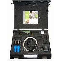
Kit Contents
Sensor, 9-pin D-sub Cable. Legris & Hausamann Connector, Power Adapter, FlowViewer CD
Tool / Board Applications
Gas Mass Flow Meter
Development Tool Type
Hardware / Software - Eval/Demo Board
Rohs Compliant
Yes
For Use With
Sensirion Type EM1NR
Lead Free Status / RoHS Status
Lead free / RoHS Compliant


EK-F3 Evaluation Kit
What You Need to Get Started
Make sure you have all of the following items before you install the hardware and FlowViewer software for
Windows 95/98/NT/2000/XP:
_
_
_
_
Additionally, software for the use of your EM1 with a PDA using Palm OS is available on our internet page
(www.sensirion.com).
Installing the Hardware
In the following section all the necessary electrical interconnections for the EM1 sensor system will be
listed. These connections are required between the EM1, a PC serial interface and a power supply.
To install your EM1 complete the following steps (see Figure 2):
The EM1 is now connected with your PC and ready to use. Proceed to the next section for a general
measurement setup. For further information on connecting the EM1 please refer to the datasheet.
Figure 2:
www.sensirion.com
1. Turn off your PC. Keep your PC plugged in so that it remains grounded while you install the EM1.
2. Connect the serial interface cable with the COM port of your PC (configuration of the serial interface
3. Turn on your PC and start Windows 95/98/2000/NT/XP.
4. Connect the interface cable with the EM1 (see also pin diagram of the EM1 given in datasheet EM1).
5. Plug in the power supply. Input 100V - 240V AC, 47Hz - 63Hz.
see datasheet EM1).
Windows 95/98/2000/NT/XP
An unused serial interface port (e.g. COM1).
FlowViewer software for Windows 95/98/NT/2000/XP on CD.
Contents of your evaluation kit as described in the Introduction.
General measurement setup for the EM1 Mass Flow Meter system. For detailed link of the
sensor system to a gas supply please refer to the next section.
to P o w e r L in e
to C O M P o rt
P o w e r S u p p ly
S e ria l In te rfa ce C o n n e cto r
In te rfa ce C a b le
C o n n e cto r
to EM1
Page 3 of 7
Related parts for EK-F3_R
Image
Part Number
Description
Manufacturer
Datasheet
Request
R

Part Number:
Description:
Sensor Evaluation Kit
Manufacturer:
SENSIRION
Datasheet:

Part Number:
Description:
Sensor Evaluation Kit
Manufacturer:
SENSIRION
Datasheet:
Part Number:
Description:
Sensor Evaluation Kit
Manufacturer:
SENSIRION
Datasheet:


Part Number:
Description:
MODULE SENSOR TEMP+HUMIDITY
Manufacturer:
Parallax Inc
Datasheet:

Part Number:
Description:
Humidity Sensor Filter Cap
Manufacturer:
SENSIRION
Datasheet:


Part Number:
Description:
Interface Modules & Development Tools Evaluation Kit for OXPCIe952
Manufacturer:
PLX Technology
Datasheet:
Part Number:
Description:
Interface Modules & Development Tools USB2.0-SATA Evaluation Kit
Manufacturer:
PLX Technology
Datasheet:
Part Number:
Description:
Interface Modules & Development Tools Evaluation Kit for OXPCIe954
Manufacturer:
PLX Technology
Datasheet: