S940700048 IDEC, S940700048 Datasheet - Page 2
S940700048
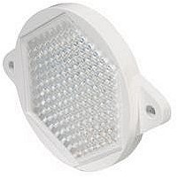
Manufacturer Part Number
S940700048
Description
Reflector
Manufacturer
IDEC
Datasheet
1.S940700048.pdf
(25 pages)
Specifications of S940700048
Reflector Type
Prismatic
Accessory Type
Reflector
For Use With
S51, S60, S62 Series Sensors
Lead Free Status / RoHS Status
Lead free / RoHS Compliant


Sensors
Dimensions (mm)
Specifi cations
Receiver
Emitter
Light Source Element
Sensing Distance
Power Voltage
Current Draw
Analog Current Output
Digital Output
Operation Mode
Response
Indicator
Detectable Object
Hysteresis
Sensitivity
Operation Point Control
Receiver Element
Operating Temperature
Storage Temperature
Operating Humidity
Extraneous Light Immunity
Noise Resistance
Insulation Resistance
Dielectric Strength
Vibration Resistance
Shock Resistance
Degree of Protection
Cable
Material
Accessories
Interference Prevention
Weight
1. Analog current output specifi cation is based on the power voltage range from 12 to 24V DC (±10%).
2. Response time for analog current output is between 10% and 90% of the rise or fall of the voltage signal when using a 249Ω resistor.
Use the attached resistor (249Ω, 1/4W) as a load resistance for converting analog output to voltage.
Red LED
Green LED
Depends on the fi ber unit (see page 173)
12 to 24V DC (Operating voltage: 10 to 30V DC) ripple 10% maximum
80mA maximum
4 to 20mA, 5V DC maximum
NPN open collector 30V DC, 100mA maximum,1.5V maximum with short circuit protection
Dark ON (connect MODE line to GND line)
Light ON (connect MODE line to power line)
0.5ms maximum
Operation LED: Red, Stable LED: Green
Translucent object, opaque object
20% maximum (using refl ex fi ber unit)
4-turn adjustment
1 turn
Photo diode
–25 to +55˚C (performance will be adversely affected if the sensor becomes coated with ice)
–30 to +70˚C (performance will be adversely affected if the sensor becomes coated with ice)
35 to 85% RH (avoid condensation)
Sunlight: 10,000 lux maximum; Incandescent light: 3,000 lux (at the receiver)
Normal mode: 500V (50ns to 1μs, 100Hz: Using a noise simulator)
Common mode: 300V (50ns to 1μs, 100Hz: Using a noise simulator)
Between live and dead parts: 20MΩ minimum, with 500V DC megger
Between live and dead parts: 1,000V, 1 minute
Damage limits: 10 to 55Hz; Single amplitude: 0.75mm 20 cycles in each of 3 axes
Damage limits: 500 m/sec
IP66—IEC Pub 529
Cable type: Ø4.4mm 5-core vinyl cabtyre cable 0.2mm2, 6’–6-3/4” (2m) long
Housing: PBT
Mounting bracket, adjusting screwdriver, load resistor (249Ω) for converting analog amperage
to voltage (1 to 5V)
Up to 2 units can be installed in close proximity. For analog output, interference prevention is
not possible.
Approximately 75g
2
2
USA: 800-262-IDEC
10 cycles in each of 3 axes
1
holes
Panel Mounting Bracket (attachment)
Canada: 888-317-IDEC
Not required for DIN Rail mounting
Fiber Optic: SA1C-FK
SA1C-FK3
–
√
√
√
√
√
√
√
√
√
√
√
√
√
√
√
√
√
√
√
√
√
√
√
√
√
√
√
√
√
Mounting Hole Layout
SA1C-FK3G
–
√
√
√
√
√
√
√
√
√
√
√
√
√
√
√
√
√
√
√
√
√
√
√
√
√
√
√
√
√
(when using a panel
mounting bracket)
165
Related parts for S940700048
Image
Part Number
Description
Manufacturer
Datasheet
Request
R

Part Number:
Description:
Cable; Between IDEC MicroSmart (port 1 or 2) and HG2F/3F/4F; 5 ft.
Manufacturer:
IDEC Corporation
Datasheet:
Part Number:
Description:
Cable; Between IDEC Micro^3C/ONC/MicroSmart (port 2) PLCs and HG2F/3F/4F; 5 ft.
Manufacturer:
IDEC Corporation
Datasheet:
Part Number:
Description:
Angled Key for Idec HS6B Safety Switch
Manufacturer:
IDEC Corporation
Datasheet:
Part Number:
Description:
Accessory, L-Shaped Key for Idec HS5B and HS5E Safety Switch
Manufacturer:
IDEC Corporation
Datasheet:
Part Number:
Description:
Accessory, Straight Key for Idec HS5B and HS5E Safety Switch
Manufacturer:
IDEC Corporation
Datasheet:
Part Number:
Description:
Straight Key for Idec HS6B Safety Switch
Manufacturer:
IDEC Corporation
Datasheet:
Part Number:
Description:
LIGHT TOWER 3 TIER RED/AMBER/GREEN 24VAC/DC WALL MOUNT
Manufacturer:
IDEC Corporation
Datasheet:
Part Number:
Description:
Flat Lens, 24V AC/DC, 1m Cable Length, Alternate: Red Green Color, IP67
Manufacturer:
IDEC Corporation
Datasheet:
Part Number:
Description:
LIGHT TOWER 2 TIER RED/GREEN 24VAC/DC WALL MOUNT
Manufacturer:
IDEC Corporation
Datasheet:
Part Number:
Description:
LIGHT TOWER 2 TIER RED/GREEN 24VAC/DC DIRECT MOUNT
Manufacturer:
IDEC Corporation
Datasheet:
Part Number:
Description:
INDICATOR INCANDESCENT LAMP, GREEN
Manufacturer:
IDEC
Datasheet:

Part Number:
Description:
LAMP, INDICATOR, INCAND, AMB
Manufacturer:
IDEC
Datasheet:
Part Number:
Description:
LAMP, INDICATOR, INCAND, GRN
Manufacturer:
IDEC
Datasheet:
Part Number:
Description:
LAMP, INDICATOR, INCAND, GRN
Manufacturer:
IDEC
Datasheet:
Part Number:
Description:
LAMP, INDICATOR, INCANDESCENT, RED
Manufacturer:
IDEC
Datasheet: