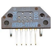
HEDL-6540#B11 Avago Technologies US Inc., HEDL-6540#B11 Datasheet
HEDL-6540#B11
Specifications of HEDL-6540#B11


Related parts for HEDL-6540#B11


HEDL-6540#B11 Summary of contents
Page 1
... The outputs of the HEDS-6500 are two single ended square waves in quadrature. The HEDL-65xx outputs are differential. The HEDS-6540 / HEDL-6540 also have a third channel index output in addition to the two quadrature outputs. This index is an active high pulse that occurs once ev- ery full rotation of the codewheel ...
Page 2
... SLOTTED (0.010) 13.2 ∅ (0.52) HEDL-54XX fig 3 65.9 (2.59) HEDS-65XX #xxx YYMM COUNTRY OF ORIGIN 24.9 (0.98) 30.2 (1.19) HEDL-65XX fig 4 24.0 ± 0.5 (192.2) 55.88 ∅ (2.200) 24.38 (0.960) 2.44 ∅ (0.096) 17.27 (0.680) ...
Page 3
... PHOTO DIODES LENS LED SIGNAL PROCESSING CIRCUITRY EMITTER CODE SECTION WHEEL There are two different connector pin-out configurations used with the HEDS-65xx / HEDL-65xx series of encoders. The table below relates the part to its connector pin-out. Connector Pin-out 3 COMPARATORS INDEX-PROCESSING CIRCUITRY DETECTOR SECTION COMPARATORS ...
Page 4
... B. Due to this integrated phasing technique, the digital output of channel quadrature with that of channel B (90 degrees out of phase). In the HEDS-6540 / HEDL-6540 the output of the com- parator for the index pulse is combined with that of the outputs of channel A and channel B to produce the final index pulse ...
Page 5
... Output Waveforms OUTPUT PHASE OUTPUT CH I OUTPUT Waveforms for Encoders without Line Drivers Waveforms for Encoders with Line Drivers. HEDL-65XX fig ROTATION HEDL-65XX fig 7 2.4 V 0.4 V 2.4 V 0.4 V 2.4 V 0.4 V ...
Page 6
... HEDL-6545 -40 to +100 Celsius -40 to +100 Celsius -. Volts -.6 to Vcc Volts mA 30,000 RPM Inch/1000 2 2 Inch/1000 HEDL-6545 -40 to +100 Celsius 4.5 to 5.5 Volts 100 100 pF 100 100 kHz ±.05 ±.05 mm (±.002) (Inch/1000) ...
Page 7
... Index Pulse Width CH I fall after fall -25°C to +100°C -40°C to +100° rise after rise -25°C to +100°C -40°C to +100°C HEDL-654x Pulse Width Error Logic State Width Error Phase Error Position Error Cycle Error Index Pulse Width *Typical values specified at Vcc = 5.0 V and 25°C. ...
Page 8
... These are tolerances required of the user. 2. Through hole in the encoder housing are also available, for longer shafts. 3. The HEDL-65X0 must be aligned using the aligning pins as specified in the section on “MOUNTING CONSIDERATIONS. ” 4. The recommended mounting screw torque for 2 screws is 1.0 Kg (0.88 in-lbs). ...
Page 9
... Mounting Considerations The HEDS-654x/HEDL-654x must be aligned with respect to the optical center (codewheel shaft) as indicated in the following figure. 2 SCREW MOUNTING M2.5 (2-56 UNC-2B) 2 PLCS – EQUALLY SPACED ON 2.62 46.00 (1.811) DIA. (0.103) BOLT CIRCLE ALIGNING PINS 2.39/2.34 DIA. – 0.76 HIGH (0.094/0.092–0.030) 15 ...
Page 10
... ALIGNMENT TOOL ASSEMBLE COMPONENTS AND MOUNTING SCREWS AND TOOLS AS APPROPRIATE. 2 LOAD ENCODER BASEPLATE ONTO RECEIVING SURFACE (MOTOR END PLATE) WITH MOUNTING SCREW HOLES ALIGNED WITH MATING HOLES. LOAD MOUNTING SCREWS AND LEAVE SLIGHTLY LOOSE. 10 HEDL-65XX fig 11 HEDL-65XX fig 12 ...
Page 11
... THE ENCODER MODULE LOCATING HOLES (ON ITS UNDERSIDE) MATE WITH THE BASEPLATE ROUND PINS. THE BASEPLATE SQUARE PINS SHOULD SEAT INTO THE ENCODER MODULE MOUNTING THRU HOLES. CONCURRENTLY, BRING THE CODEWHEEL DOWN ONTO THE MATING SHAFT. 11 LOCATE ENCODER BASEPLATE LOCATE ENCODER MODULE AND CODEWHEEL HEDL-65XX fig 13 HEDL-65XX fig 14 ...
Page 12
... HEDL-65XX fig 15 WITH CODEWHEEL AND ENCODER MODULE IN PLACE, LOAD ENCODER HOUSING FROM TOP INTO "SNAPPED" POSITION. INSURE THAT ANY CABLES FROM THE ENCODER MODULE ARE FOLDED DOWN SUCH THAT THEY EMERGE FROM THE BOTTOM OF THE HOUSING'S REAR RECTANGULAR PORT. HEDL-65XX fig 16 ...
Page 13
... THROUGH HOLE 0 – – None 4 – – 13.3 mm (0.525 in.) 05 HEDS-6500 HEDS-6505 HEDS-6540 HEDS-6545 Encoders Film Codewheel (up to 70°C) HEDM – 65 THROUGH HOLE OUTPUTS 0 – None 0 – – 13 – (0.525 in) 05 HEDM-6500 HEDM-6505 HEDM-6540# T HEDM-6545# T RESOLUTION (CYCLES/REV 500 B = 1000 J = 1024 06 08 ...
Page 14
... Ordering Information for 2CH and 3CH Encoder Modules with Line Driver Encoders with Metal Codewheel (up to 100°C) HEDL - 65 OUTPUTS THROUGH HOLE 0 – – None 4 – – 13.3 mm (0.525 in HEDL-6540# B HEDL-6545 Ordering Information for HEDS=76XX Centering Tools HEDS-6510 Option 0 SHAFT DIAMETER 05 – ...