SIP21106DR-30-E3 Vishay, SIP21106DR-30-E3 Datasheet - Page 13
SIP21106DR-30-E3
Manufacturer Part Number
SIP21106DR-30-E3
Description
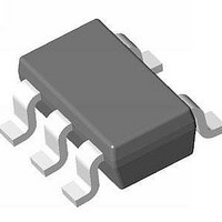
IC LDO REG 150MA 3.0V LN SC70-5L
Manufacturer
Vishay
Datasheet
1.SIP21106DR-33-E3.pdf
(15 pages)
Specifications of SIP21106DR-30-E3
Regulator Topology
Positive Fixed
Voltage - Output
3V
Voltage - Input
Up to 6V
Voltage - Dropout (typical)
0.16V @ 150mA
Number Of Regulators
1
Current - Output
150mA
Current - Limit (min)
170mA
Operating Temperature
-40°C ~ 85°C
Mounting Type
*
Package / Case
*
Number Of Outputs
1
Polarity
Positive
Input Voltage Max
6 V
Output Voltage
3 V
Output Type
Fixed
Dropout Voltage (max)
0.18 V at 150 mA
Output Current
150 mA
Line Regulation
0.2 % / V
Load Regulation
0.006 % / mA
Voltage Regulation Accuracy
1 %
Maximum Power Dissipation
0.187 W
Maximum Operating Temperature
+ 85 C
Mounting Style
SMD/SMT
Minimum Operating Temperature
- 40 C
Lead Free Status / RoHS Status
Lead free / RoHS Compliant


DETAILED DESCRIPTION
As shown in the block diagram, the circuit consists of a
bandgap
transistor and an internal feedback resistor voltage divider,
which is used to monitor and control the output voltage.
A constant 1.2 V bandgap reference voltage is applied to the
non-inverting input of the error amplifier. The error amplifier
compares this reference with the feedback voltage on its
inverting input and amplifies the difference. If the feedback
voltage
pass-transistor gate is pulled low. This increases the
PMOS's gate to source voltage and allows more current to
pass through the transistor to the output which increases the
output voltage. Conversely, if the feedback voltage is higher
than the reference voltage, the pass transistor gate is pulled
high, decreasing the gate-to-source voltage, thereby
allowing less current to pass to the output and causing it to
drop.
Internal P-Channel Pass Transistor
A 0.9 Ω (typical) P-channel MOSFET is used as the pass
transistor for the SiP21106, SiP21107, SiP21108 part series.
The MOSFET transistor offers many advantages over the
more, formerly, common PNP pass transistor designs, which
ultimately result in longer battery lifetime. The main
disadvantage of PNP pass transistors is that they require a
certain base current to stay on, which significantly increases
under heavy load conditions. In addition, during dropout,
when the pass transistor saturates, the PNP regulators
waste
MOSFETS require virtually zero-base drive and do not suffer
from the stated problems. These savings in base drive
current translate to lower quiescent current which is typical
around 35 µA as shown in the Typical Characteristics.
Shutdown and Auto-Dischage/No-Discharge
Bringing the EN voltage low will place the part in shutdown
mode where the device output enters a high-impedance
state and the quiescent current is reduced to below 1 µA,
reducing the drain on the battery in standby mode and
increasing standby time. Connect EN pin to input for normal
operation. The output has an internal pull down to discharge
the output to ground when the EN pin is low. The internal pull
down is a 100 Ω typical resistor, which can discharge a 1 µF
in less than 1 ms. Refer to Typical Operating Waveforms for
turn-off waveforms.
Output Voltage Selection
The SiP21106 has fixed voltage outputs that are preset to
voltages from 1.2 V to 4.6 V (see Ordering Information).
Document Number: 74442
S09-1047-Rev. G, 08-Jun-09
considerable
is
reference,
lower
than
error
current.
the
amplifier,
In
reference
contrast,
P-channel
voltage,
P-channel
pass
the
The SiP21108 has a user-adjustable output that can be set
through the resistor feedback network consisting of R
R
consistent with ground current specification. R
determined by the following equation:
Where V
for better output voltage accuracy (see Figure 4).
Current Limit
The SiP21106, SiP21107, SiP21108 include a current limit
block which monitors the current passing through the pass
transistor through a current mirror and controls the gate
voltage of the MOSFET, limiting the output current to 330 mA
(typical). This current limit feature allows for the output to be
shorted to ground for an indefinite amount of time without
damaging the device.
Thermal-Overload Protection
The thermal overload protection limits the total power
dissipation and protects the device from being damaged.
When the junction temperature exceeds T
device turns the P-channel pass transistor off allowing the
device to cool down. Once the temperature drops by about
20 °C, the thermal sensor turns the pass transistor on again
and resumes normal operation. Consequently, a continuous
thermal overload condition will result in a pulsed output. It is
generally recommended to not exceed the junction
temperature rating of 125 °C for continuous operation.
Noise Reduction in SiP21106
For the SiP21106, an external 10 nF bypass capacitor at BP
pin is used to create a low pass filter for noise reduction. The
startup time is fast, since a power-on circuit pre-charges the
bypass capacitor. After the power-up sequence the
pre-charge circuit is switched to standby mode in order to
save current. It is therefore not recommended to use larger
bypass capacitor values than 50 nF. When the circuit is used
without a capacitor, stable operation is guaranteed.
R = R x
2
1
SiP21106, SiP21107, SiP21108
. R
Reference
1.2 V
2
2
range of 100K to 400K is recommended to be
ref
is typically 1.2005 V. Use 1 % or better resistors
(
V
V
OUT
ref
- 1
Error-Amp
-
+
)
Figure 4.
Vishay Siliconix
R
V
R
IN
1
J
2
www.vishay.com
= 150 °C, the
1
can then be
V
OUT
1
and
13
Related parts for SIP21106DR-30-E3
Image
Part Number
Description
Manufacturer
Datasheet
Request
R

Part Number:
Description:
IC LDO REG 150MA 3.3V LN SC70-5L
Manufacturer:
Vishay
Datasheet:

Part Number:
Description:
IC LDO REG 150MA 1.2V LN SC70-5L
Manufacturer:
Vishay
Datasheet:
Part Number:
Description:
IC LDO REG 150MA 1.8V LN SC70-5L
Manufacturer:
Vishay
Datasheet:
Part Number:
Description:
IC LDO REG 150MA 2.5V LN SC70-5L
Manufacturer:
Vishay
Datasheet:
Part Number:
Description:
IC LDO REG 150MA 2.6V LN SC70-5L
Manufacturer:
Vishay
Datasheet:
Part Number:
Description:
IC LDO REG 150MA 2.85V LN SC705L
Manufacturer:
Vishay
Datasheet:
Part Number:
Description:
IC LDO REG 150MA 2.8V LN SC70-5L
Manufacturer:
Vishay
Datasheet:
Part Number:
Description:
IC LDO REG 150MA 4.5V LN SC70-5L
Manufacturer:
Vishay
Datasheet:
Part Number:
Description:
IC LDO REG 150MA 4.6V LN SC70-5L
Manufacturer:
Vishay
Datasheet:
Part Number:
Description:
IC LDO REG 150MA 4.75V LN SC705L
Manufacturer:
Vishay
Datasheet:

Part Number:
Description:
357-036-542-201 CARDEDGE 36POS DL .156 BLK LOPRO
Manufacturer:
Vishay
Datasheet:
Part Number:
Description:
357-036-542-201 CARDEDGE 36POS DL .156 BLK LOPRO
Manufacturer:
Vishay
Datasheet:
Part Number:
Description:
357-036-542-201 CARDEDGE 36POS DL .156 BLK LOPRO
Manufacturer:
Vishay
Datasheet:
Part Number:
Description:
357-036-542-201 CARDEDGE 36POS DL .156 BLK LOPRO
Manufacturer:
Vishay
Datasheet:
Part Number:
Description:
357-036-542-201 CARDEDGE 36POS DL .156 BLK LOPRO
Manufacturer:
Vishay
Datasheet: