MQ-W3C-DC12-24V PANASONIC EW, MQ-W3C-DC12-24V Datasheet - Page 6
MQ-W3C-DC12-24V
Manufacturer Part Number
MQ-W3C-DC12-24V
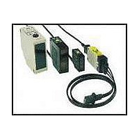
Description
Photoelectric Sensor
Manufacturer
PANASONIC EW
Datasheet
1.MQ-W20A-DC12-24V.pdf
(6 pages)
Specifications of MQ-W3C-DC12-24V
Output Current
100mA
Sensor Output
PNP
Supply Voltage Range Dc
12V To 24V
Sensor Housing
Square
Sensor Input
Optical
Output Type
Transistor
Sensing Range Max
30mm
Mounting Type
Bracket
Lead Free Status / RoHS Status
Lead free / RoHS Compliant


CAUTIONS
1. Ambient environment
1) Use within the range of ambient
temperature of –25 to +55°C
+131°F.
2) Use within a range of 9.6 V to 30 V
DC (ripple P-P included) for operating
voltage.
3) Use with an ambient light level at the
light receiving surface of less than
10,000 lux for incandescent lamp and
less than 30,000 lux for sunlight.
4) Use a surge absorber as the internal
circuit may be damaged if external
surge voltage exceeds 500 V
[±(1.2i50) µs of single polarity full-
wave voltage].
5) Avoid using in a location with high
concentrations of steam, dust, or corro-
sive gas.
6) The sensor is of immersion protected
type, but this does not mean that it can
be used in water or where there is
direct impingement of rain for detecting
objects.
2. Connections
1) Check all wiring before applying
power since incorrect wiring may dam-
age the internal circuit.
2) Use a load relay with a rated operat-
ing voltage of 12 V DC or 24 V DC. The
voltage applied to the load relay is the
operating voltage of the photoelectric
sensor minus the internal voltage drop
(1.2 V). Voltage fluctuations should be
taken into account.
These products are not
safety sensors and are
not designed or intended
to be used to protect life
and prevent bodily injury
or property damage.
–13 to
3) If a load greater than 100 mA is con-
nected, the output section will be
damaged, so sufficient care should be
taken.
4) If the wiring to the photoelectric sen-
sors run parallel to high voltage or
power lines, due to inductive noise,
mis-operation or damage can occur.
Wiring should be run in separate.
5) Wire 0.3 mm
larger should be used for wiring up to a
length of 100 m
6) When the photoelectric sensors
being mounted, if the unit is struck by a
hammer or other heavy tool, the func-
tion can be impaired. Sufficient care
should be taken.
7) The changeover from Light-ON (light
entry ON) to Dark-ON (light intercepted
OFF) can be carried out with the pink
lead wire. For Light-ON, connect the
pink wire to the B side, and for Dark-
ON, connect the pink wire to the v
side.
3. Distance adjustment
1) Set the detecting surface of the pho-
toelectric sensor in the detecting direc-
tion and temporarily fasten it.
2) While no target in the detection
region, set the distance adjustment dial
to maximum (FAR) and slowly turn it
counterclockwise.
Continue turning the control counter-
clockwise until the operation indicator
LED (OPE.) is extinguished. This is the
adjustment position. If the indicator
LED is extinguished at the maximum
position, that is the adjustment position.
3) With target in the detection area, set
the dial in the minimum position
(NEAR) and turn the control clockwise
to locate the position where the indica-
tor LED turns ON. If the indicator LED
goes ON at the minimum position, then
NEAR is the adjustment position.
4) Set the control to a point midway
between the locations found in 2) and
3) above.
5) Securely fasten the photoelectric
sensor. When fastening, the sensor
should be sufficiently secure so that it
will not shift under vibration of shock.
2
328
.0005 inch
03/2003
ft..
2
AWG22 or
Notes:
1. If the adjustment indicator LED does
not light in the adjustment of 3) as pre-
scribed, or if the position between 2)
and 3) is less than 2 graduations,
change the position of the detection
surface and repeat the procedure of 1)
to 4), or try to determine the source of
external factors such as variation in
ambient temperature, variation in target
position, etc., that creating the problem.
2. The difference in detection distance
due to the colors of the target is virtual-
ly non-existent, but if the actual target is
one where the reflectivity is extremely
low (target which have a frosted finish
produced by black rubber), or where
the reflectivity is extremely high (mirror,
glass, or truly reflectting target), confir-
mation should be done with the actual
target.
4. Detector
1) Keep the detector surface clean as
excessive dust or dirt on the detector
surface will decrease the margin of the
distance range.
2) The front surface of the lens is made
of polycarbonate. This material is resis-
tant to water, weak acids and alkalis,
aliphatic hydrocarbons, oils, etc., but it
is not resistant to ketones, esters, halo-
genated hydrocarbons, or aromatic
hydrocarbons.
MQ-W70 type
Distance adjustment dial
Distance adjustment dial
MQ-W3 type
MW-W20 type
MQ-W
Operation
Indicator LED
Operation
Indicator LED
Adjustment
indicator LED
Adjustment
indicator LED
185
Related parts for MQ-W3C-DC12-24V
Image
Part Number
Description
Manufacturer
Datasheet
Request
R

Part Number:
Description:
AREA REFL PNP IR 3CM WIRE SEL 2MS - Internally Grounded
Manufacturer:
PANASONIC EW

Part Number:
Description:
POWER RELAY, 24VDC, 30A, SPST-NO
Manufacturer:
PANASONIC EW
Datasheet:

Part Number:
Description:
POWER RELAY, SPDT, 12VDC, 10A, PC BOARD
Manufacturer:
PANASONIC EW
Part Number:
Description:
POWER RELAY, 24VDC, 5A, SPST-NO, PCB
Manufacturer:
PANASONIC EW
Datasheet:


Part Number:
Description:
SIGNAL RELAY, DPDT, 4.5VDC, 1A, SMD
Manufacturer:
PANASONIC EW
Datasheet:

Part Number:
Description:
SIGNAL RELAY, DPDT, 4.5VDC, 1A, THD
Manufacturer:
PANASONIC EW
Datasheet:

Part Number:
Description:
MINIATURE RELAY, DPDT, 24VDC, 2A, THD
Manufacturer:
PANASONIC EW


Part Number:
Description:
SIGNAL RELAY, DPDT, 5VDC, 2A, PC BOARD
Manufacturer:
PANASONIC EW
Datasheet:
Part Number:
Description:
SIGNAL RELAY, DPDT, 5VDC, 2A, PC BOARD
Manufacturer:
PANASONIC EW
Datasheet:


Part Number:
Description:
PHOTOMOS RELAY, 60VDC, 400mA
Manufacturer:
PANASONIC EW
Datasheet:

Part Number:
Description:
PHOTOMOS RELAY, 400V, 150mA
Manufacturer:
PANASONIC EW
Datasheet: