SM2A912LV BANNER ENGINEERING, SM2A912LV Datasheet - Page 6
SM2A912LV
Manufacturer Part Number
SM2A912LV
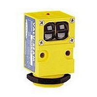
Description
Photoelectric Sensor
Manufacturer
BANNER ENGINEERING
Datasheet
1.SM2A912LV.pdf
(8 pages)
Specifications of SM2A912LV
Output Current
250mA
Sensor Output
SPST SCR
Sensing Range Max
9m
Switch Terminals
Quick Connect
Sensing Range Min
0.15m
Sensor Input
Optical
Sensing Mode
Retroreflective


VALU-BEAM
6
ac/dc vb-emitter w/cable.eps
Supply Voltage and Current
Supply Protection Circuitry
Output Configuration
Output Rating
Output Protection Circuitry
Output Response Time
Repeatability
Adjustments
Indicators
Construction
Environmetal Rating
Connections
Operating Conditions
Application Notes
Certifications
P/N 03467 rev. E
Other AC Models – Cabled
Emitters – Cabled
bn
bu
bn
bu
Load
®
24-250V ac
Sensors – 912 Series
10-250V ac/dc
+
–
24 to 250V ac (50/60 Hz), except for SMA91E, ESR and EF emitters, which operate from 10 to 250V ac or dc
Protected against transient voltages
SPST SCR solid-state relay with either normally closed or normally open contact
(light/dark operate selectable); 2-wire hookup
Minimum load current 10 mA, max. steady-state load capability 750 mA to 50° C ambient (122° F),
500 mA to 70° C ambient (158° F)
Inrush capability: 4 amps for 1 second (non-repetitive)
Off-state leakage: current less than 1.7 mA rms
On-state voltage drop: ≤ 5 volts rms at 750 mA load, ≤ 10 volts rms at 15 mA load
Protected against false pulse on power-up
Receivers only: 8 milliseconds 0N and 4 milliseconds OFF, independent of signal strength
All other models: 8 milliseconds ON and OFF
OFF time does not include load response of up to 1/2 ac cycle (8.3 milliseconds).
Response time specification of the load should be considered when total response time is important.
NOTE: 300 millisecond delay on power-up; outputs do not conduct during this delay.
Opposed and Glass Fiber Optic Emitter-Receiver pairs: 1.0 millisecond
Retro, Diffuse, Convergent and Glass Fiber Optic: 2.6 milliseconds
Light/Dark Operate select switch and Sensitivity control potentiometer, both located at rear of sensor
Top-mounted red LED indicator lights when output is conducting.
Model SMA91E and SM91ESR emitters: visible-red “tracer beam” indicates “Power ON” and enables line-of-
sight alignment.
Reinforced thermoplastic polyester housing, totally encapsulated, molded acrylic lenses and stainless steel
hardware
Meets NEMA standards 1, 2, 3, 3S, 4, 4X, 12 and 13; IEC IP66
PVC-jacketed 2 m (6.5') or 9 m (30') cables or 3-pin Mini-style (QD) fitting available. See page 7.
Temperature: -20° to +70° C (-4° to +158° F) Maximum relative humidity: 90% at 50° C (non-condensing)
i) 912 Series ac sensors can be destroyed from overload conditions.
ii) Use on low voltage requires careful analysis of the load to determine if the leakage current or on-state
iii) The false-pulse protection feature may cause momentary drop-out of the load when the sensor is wired in
series or parallel with mechanical switch contacts.
voltage of the sensor will interfere with proper operation of the load.
ac/dc vb-emitter w/qd.eps
Specifications – AC Models
Other AC Models – QD
(3-Pin Mini-Style)
(3-Pin Mini-Style)
AC Hookups
Emitters – QD
bn
bu
bk
bn
bu
bk
Load
24-250V ac
10-250V ac/dc
–
+
+
–
Banner Engineering Corp.
www.bannerengineering.com • Tel: 763.544.3164
Blue Wire
Black Wire
(Cable Connector Shown)
3-Pin Mini-Style Pinout
•
Minneapolis, MN U.S.A.
Brown Wire
Related parts for SM2A912LV
Image
Part Number
Description
Manufacturer
Datasheet
Request
R

Part Number:
Description:
Photoelectric Sensor
Manufacturer:
BANNER ENGINEERING
Datasheet:

Part Number:
Description:
Photoelectric Sensor
Manufacturer:
BANNER ENGINEERING
Datasheet:

Part Number:
Description:
LEDIR70XD4-XM-81039 MAX INTENS STROBE ONLY NO BANNER MARKS
Manufacturer:
BANNER ENGINEERING
Part Number:
Description:
M18SP6DL-72225 LABELED MOELLER NO BANNER MARKINGS BULK PACK
Manufacturer:
BANNER ENGINEERING
Part Number:
Description:
M18SP6DLQ-72226 LABLED MOELLER NO BANNER MARKINGS BULK PACK
Manufacturer:
BANNER ENGINEERING
Part Number:
Description:
M18SP6L-72223 LABELED MOELLER NO BANNER MARKINGS BULK PACK
Manufacturer:
BANNER ENGINEERING
Part Number:
Description:
M18SP6LQ-72224 LABELED MOELLER NO BANNER MARKINGS BULK PACK
Manufacturer:
BANNER ENGINEERING
Part Number:
Description:
P4D1-77908 P4 DRIVER GENERIC NO BANNER MARKINGS RESALE TO CUSTOMER
Manufacturer:
BANNER ENGINEERING
Part Number:
Description:
Photoelectric Sensor
Manufacturer:
BANNER ENGINEERING
Datasheet:

Part Number:
Description:
Programmable Indicator Light
Manufacturer:
BANNER ENGINEERING
Datasheet:
Part Number:
Description:
INDICATOR LED PANEL 50MM GRN/RED/YEL 30V
Manufacturer:
BANNER ENGINEERING
Datasheet:
Part Number:
Description:
Programmable Indicator Light
Manufacturer:
BANNER ENGINEERING
Datasheet: