SM31RLQD BANNER ENGINEERING, SM31RLQD Datasheet - Page 2
SM31RLQD
Manufacturer Part Number
SM31RLQD
Description
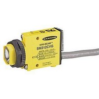
Photoelectric Sensor
Manufacturer
BANNER ENGINEERING
Type
Reflectiver
Specifications of SM31RLQD
Output Current
150mA
Sensor Output
NPN/PNP
Supply Voltage Range Dc
10V To 30V
Sensor Input
Optical
Output Type
NPN/PNP, NO/NC
Supply Voltage Max
30VDC
Sensing Range Max
30m
Switch Terminals
Quick Connect
Brand/series
Mini-Beam®
Current, Switching
150 mA
Ip Rating
IP67
Mounting Type
Threaded
Output
NPN/PNP
Primary Type
Photoelectric
Range, Measurement
30 m
Sensing Mode
Opposed
Technology
Photoelectric
Termination
4-Wire Connector
Voltage, Supply
30 VDC
Operating Temperature
–4°F to 158°F
Operation Mode
Light or Dark Operate
Response Time
DC — 1 mSec.; AC/DC — 20 mSec.
Lead Free Status / Rohs Status
RoHS Exempt Product


MINI-BEAM
Proper operation of the sensors requires that they be mounted
securely and aligned properly. Excessive movement or vibration
can cause intermittent or false operation due to loss of alignment.
For maximum mechanical stability, final-mount these sensors in
18-mm holes by their threaded barrels or use a mounting bracket
(see page 6).
page
1) Begin with the emitter mounted securely in place. For
2) Apply power to the emitter and receiver, and advance the
3) Repeat the alignment motions after each GAIN reduction.
2
small-parts counting applications, stretch a string
between the emitter and receiver lenses to ensure that the
sensing beam will pass through the center of the sensing
location. For less critical applications, the receiver may be
initially positioned by line-of-sight placement. Mount the
receiver, leaving a means for movement.
receiver’s 15-turn GAIN control to maximum (clockwise
end of rotation). The GAIN control is clutched at both
ends to avoid damage, and will “free-wheel” when either
endpoint is reached.
If the receiver is “seeing” the emitter’s light beam, the
receiver alignment LED should be “on”. Move the receiver
up-down-right-left (include angular rotation) to obtain the
fastest receiver LED pulse rate. If a pulse is not
observable (too fast to count), reduce the GAIN control
(counterclockwise rotation) to obtain a countable pulse
rate of one to five beats per second. Note: to aid
alignment at short ranges, it may help to further reduce
the strength of the light signal by temporarily masking
the emitter and/or receiver lens with tape or a sheet of
paper.
When you have found the receiver orientation that
produces the fastest pulse rate, mount the receiver solidly
in that position. Remove any masking material, and
increase the receiver GAIN to maximum. Test the system
by placing the object to be detected into the sensing
position. The receiver LED indicator should go “off”. If it
does not go “off”, the cause is probably either “flooding”
or “burn-through”.
Flooding occurs when a portion of the effective beam
passes around the object to be sensed and activates the
receiver. Check that the object completely breaks the
beam, and that the beam is centered on the object. Add
apertures, if necessary, to tailor the effective beam to the
size or profile of the object being sensed. Burn-through
refers to a portion of the emitter’s light energy passing
through a thin or translucent object and activating the
receiver. Try sensing at a reduced GAIN setting or
consider an alternative sensing scheme.
®
Sensors
SM31E/SM31R and SM31EL/SM31RL
MINI-BEAM Installation and Alignment
* Note regarding Light/Dark operate switch:
Emitter
• Turn switch fully clockwise for light operate (sensor
• Turn switch fully counterclockwise for dark operate
outputs conduct when sensing light is received)
(sensor outputs conduct when sensing light is not
received)
sensor sees the reflection of its own modulated
light and pulses at a rate proportional to the
Receiver
“AID” Indicator LED lights when the
strength of the received light signal
Banner Engineering Corp.
www.bannerengineering.com • Tel: 763.544.3164
Opposed Mode Alignment
Move receiver to obtain the
fastest LED pulse rate.
•
Minneapolis, U.S.A.
Receiver
15 Turn
Gain
Adjustment
and Light/Dark
Operate Switch*
Gasketed
Acrylic Cover
L e
f t
D o
U p
w n
R i
g h
t
Related parts for SM31RLQD
Image
Part Number
Description
Manufacturer
Datasheet
Request
R

Part Number:
Description:
SM31RL-52296 400MM CONN ASSY
Manufacturer:
BANNER ENGINEERING

Part Number:
Description:
Photoelectric Sensor
Manufacturer:
BANNER ENGINEERING
Datasheet:
Part Number:
Description:
SM31R-26885 DC MINIBEAM GLASS LENS FOR FOREMOST PKG
Manufacturer:
BANNER ENGINEERING
Part Number:
Description:
Photoelectric Sensor
Manufacturer:
BANNER ENGINEERING
Datasheet:

Part Number:
Description:
Photoelectric Sensor
Manufacturer:
BANNER ENGINEERING
Datasheet:

Part Number:
Description:
Photoelectric Sensor
Manufacturer:
BANNER ENGINEERING
Datasheet:
Part Number:
Description:
LEDIR70XD4-XM-81039 MAX INTENS STROBE ONLY NO BANNER MARKS
Manufacturer:
BANNER ENGINEERING
Part Number:
Description:
M18SP6DL-72225 LABELED MOELLER NO BANNER MARKINGS BULK PACK
Manufacturer:
BANNER ENGINEERING
Part Number:
Description:
Photoelectric Sensor
Manufacturer:
BANNER ENGINEERING
Datasheet:

Part Number:
Description:
Programmable Indicator Light
Manufacturer:
BANNER ENGINEERING
Datasheet:
Part Number:
Description:
INDICATOR LED PANEL 50MM GRN/RED/YEL 30V
Manufacturer:
BANNER ENGINEERING
Datasheet:
Part Number:
Description:
Programmable Indicator Light
Manufacturer:
BANNER ENGINEERING
Datasheet: