E2F-X5E1 Omron, E2F-X5E1 Datasheet - Page 2
E2F-X5E1
Manufacturer Part Number
E2F-X5E1
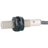
Description
Inductive Proximity Sensor
Manufacturer
Omron
Series
E2Fr
Type
Plastic Cylindrical Inductiver
Specifications of E2F-X5E1
Sensor Input
Inductive
Sensing Range
5mm
Supply Voltage Range Dc
10V To 30V
Mounting Type
Bracket
Switch Terminals
Wire Leaded
Sensing Face Diameter
18mm
Supply Voltage Min
10VDC
Maximum Operating Temperature
+ 70 C
Supply Voltage
30 V
Operating Supply Voltage
10 V to 30 V
Sensing Distance
5 mm
Minimum Operating Temperature
- 25 C
Features
High visibility indicator
Sensor Type
Inductive
Sensing Object
Metallic
Response Frequency
600Hz
Material - Body
Plastic
Shielding
Shielded
Voltage - Supply
10 V ~ 30 V
Output Type
NPN-NO
Terminal Type
3-Wire
Package / Case
M18
Sensing Range Max
5mm
Rohs Compliant
Yes
Lead Free Status / RoHS Status
Lead free / RoHS Compliant


Ratings and Specifications
*1. The response frequency is an average value. Measurement conditions are as follows: standard sensing object, a distance of twice the standard sensing object, and
*2. When using the Sensor in environments subject to splashing cutting oil, deterioration may result due to the additives in the oil. The E2E is recommended in such
Item
Sensing distance
Set distance
Differential travel
Detectable object
Standard sensing
object
Response frequency
*1
Power supply voltage
(operating voltage
range)
Current consumption
Leakage current
Control
output
Indicators
Operation mode
(with sensing object
approaching)
Protection circuits
Ambient
temperature range
Ambient
humidity range
Temperature influence ±10% max. of sensing distance at 23°C in the temperature range of −25 to 70°C
Voltage influence
Insulation resistance
Dielectric strength
Vibration resistance
Shock resistance
Degree of protection
Connection method
Weight (packed state)
Materials
Accessories
a set distance of half the sensing distance.
environments.
OMRON Test Method
Usage conditions: 10 m or less under water in natural conditions
1. No water ingress after 1 hour under water at 2 atmospheres of pressure.
2. Sensing distance and insulation resistance specifications must be met after 20 repetitions of 1 hour in 0°C water and 1 hour in 70°C water.
Load
current
Residual
voltage
Case
Sensing
surface
Clamping
nuts
Model
1.5 mm ±10%
0 to 1.2 mm
10% max. of sensing distance
Ferrous metal (The sensing distance decreases with non-ferrous metal. Refer to Engineering Data on page 3.)
Iron, 8 × 8 × 1 mm
E Models: 2 kHz,
Y Models: 25 Hz
E Models: 12 to 24 VDC (10 to 30 VDC), ripple (p-p): 10% max.
Y Models: 24 to 240 VAC (20 to 264 VAC)
E Models: 17 mA max.
Y Models: 1.7 mA max. at 200 VAC (Refer to Engineering Data on page 3.)
E Models: 200 mA max.
Y Models: 5 to 100 mA
E Models: 2 V max. (Load current: 200 mA, Cable length: 2 m)
Y Models: Refer to Engineering Data on page 4.
E Models: Detection indicator (red)
Y Models: Operation indicator (red)
E1/Y1 Models: NO
E2/Y2 Models: NC
E Models: Reverse polarity protection, Load short-circuit protection, Surge suppressor; Y Models: None
Operating/Storage: −25 to 70°C (with no icing or condensation)
Operating/Storage: 35% to 95%
E Models: ±2.5% max. of sensing distance at rated voltage in rated voltage ±15% range
Y Models: ±1% max. of sensing distance at rated voltage in rated voltage ±10% range
50 MΩ min. (at 500 VDC) between current-carrying parts and case
E Models:
Y Models: (M8 Models): 2,000 VAC, 50/60 Hz for 1 min between current-carrying parts and case
(Other M8 Models):
Destruction: 10 to 55 Hz, 1.5-mm double amplitude for 2 hours each in X, Y, and Z directions
Destruction: 1,000 m/s
IEC 60529 IP68, in-house standards: oil-resistant
Pre-wired Models (Standard cable length: 2 m)
Approx. 40 g
Polyarylate resin
Polyacetal
Instruction manual
E2F-X1R5E@
E2F-X1R5Y@
Refer to the timing charts under I/O Circuit Diagrams on page 4 for details.
2
10 times each in X, Y, and Z directions
1,000 VAC, 50/60 Hz for 1 min between current-carrying parts and case
4,000 VAC, 50/60 Hz for 1 min between current-carrying parts and case
2 mm ±10%
0 to 1.6 mm
Iron, 12 × 12 × 1 mm
E Models: 1.5 kHz,
Y Models: 25 Hz
Approx. 50 g
E2F-X2E@
E2F-X2Y@
5 mm ±10%
0 to 4 mm
Iron, 18 × 18 × 1 mm
E Models: 600 Hz,
Y Models: 25 Hz
E Models: 200 mA max.
Y Models: 5 to 300 mA
Approx. 130 g
E2F-X5E@
E2F-X5Y@
10 mm ±10%
0 to 8 mm
Iron, 30 × 30 × 1 mm
E Models: 400 Hz,
Y Models: 25 Hz
Approx. 170 g
E2F-X10E@
E2F-X10Y@
E2F
2
Related parts for E2F-X5E1
Image
Part Number
Description
Manufacturer
Datasheet
Request
R

Part Number:
Description:
Proximity Sensors INDUCTIVE M8 SCR
Manufacturer:
Omron
Datasheet:

Part Number:
Description:
Proximity Sensor
Manufacturer:
Omron
Datasheet:
Part Number:
Description:
Proximity Sensor
Manufacturer:
Omron
Datasheet:
Part Number:
Description:
Proximity Sensor
Manufacturer:
Omron
Datasheet:
Part Number:
Description:
Inductive Proximity Sensor
Manufacturer:
Omron
Datasheet:

Part Number:
Description:
Inductive Proximity Sensor
Manufacturer:
Omron
Datasheet:
Part Number:
Description:
Inductive Proximity Sensor
Manufacturer:
Omron
Datasheet:
Part Number:
Description:
Inductive Proximity Sensor
Manufacturer:
Omron
Datasheet:
Part Number:
Description:
Inductive Proximity Sensor
Manufacturer:
Omron
Datasheet:
Part Number:
Description:
Inductive Proximity Sensor
Manufacturer:
Omron
Datasheet:

Part Number:
Description:
PROX PLASTIC M8,1.5mm NPN(COO)
Manufacturer:
Omron
Datasheet:
Part Number:
Description:
PROX PLASTIC M30,10mm NPN-NC
Manufacturer:
Omron
Datasheet: