TL-T2E15 Omron, TL-T2E15 Datasheet - Page 2
TL-T2E15
Manufacturer Part Number
TL-T2E15
Description
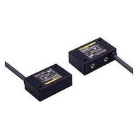
Inductive Proximity Sensor
Manufacturer
Omron
Series
TL-Tr
Specifications of TL-T2E15
Sensor Input
Inductive
Sensing Range
2mm
Supply Voltage Range Dc
10V To 30V
Sensing Range Max
2mm
Sensor Housing
Rectangular
Switch Terminals
Cable
Sensor Output
NPN Voltage-Current Output
Sensing Distance
0.079" (2mm)
Sensor Type
Inductive
Sensing Object
Metallic
Response Frequency
800Hz
Material - Body
ABS Resin
Shielding
Shielded
Voltage - Supply
10 V ~ 30 V
Output Type
NPN-NO
Terminal Type
3-Wire
Package / Case
Box
Lead Free Status / RoHS Status
Lead free / RoHS Compliant


Ratings and Specifications
Item
Sensing distance
Setting distance
Differential travel
Sensing object
Standard sensing object
Response frequency
Supply voltage
(operating voltage range)
Current consumption
Leakage current
Control
output
Indicators
Operation mode
(with sensing object ap-
proaching)
Circuit protection
Ambient temperature
Ambient humidity
Temperature influence
Voltage influence
Insulation resistance
Dielectric strength
Vibration resistance
(destruction)
Shock resistance
(destruction)
Degree of protection
Connection method
Weight (packed state)
Material
Accessories
Switching
capacity
Residual
voltage
Case
Sensing surface
http://www.ia.omron.com/
Model
TL-T2E1
TL-T2E2
TL-T2F1
2 mm±10%
0 to 1.6 mm
10% max. of sensing distance
Ferrous metal (The sensing distance decreases with non-ferrous metal. Refer to Engineering Data on
page 3.)
Iron 12 × 12 × 1 mm
E and F models: 800 Hz,
Y models: 20 Hz
E and F models: 12 to 24 VDC (10 to 30 VDC), ripple (p-p): 20% max.
Y models:
E and F models: 15 mA max. at 24 VDC
Y models: 2.5 mA max. at 200 VAC
E and F models: 100 mA max. at 12 VDC, 200 mA max. at 24 VDC
Y models:
E and F models: 1.0 V max. with a load current of 100 mA and cord length of 2 m
Y models:
Detection indicator (red)
E1 models: NO
E2 models: NC
F1 models: NO
Y1 models: NO
Y2 models: NC
E models: Reverse connection protection and surge absorber
Y models: Surge absorber
Operating/Storage: −25°C to 70°C (with no icing or condensation)
Operating/Storage: 35% to 95% (with no condensation)
±10% max. of sensing distance at 23% in the temperature range of −25 to 70°C
E and F models: ±2.5% max. of sensing distance within a range of ±15% of the rated power supply voltage
Y models:
50 MΩ min. (at 500 VDC) between case and current-carrying parts
E and F models: 1,000 VAC, 50/60 Hz for 1 min between case and current-carrying parts
Y models:
10 to 55 Hz, 1.5-mm double amplitude for 2 hours each in X, Y, and Z directions
500 m/s
IEC IP67, in-house standard for oil-resistance
Pre-wired Models (Standard cable length: 2 m)
Approx. 70 g
Heat-resistant ABS resin
Instruction sheet
2
for 10 times each in X, Y, and Z directions
100 to 220 VAC (90 to 250 VAC) 50/60 Hz
10 to 200 mA
Refer to Residual Voltage (Typical) on page 3.
±2.5% max. of sensing distance within a range of ±10% of the rated power supply voltage
2,000 VAC, 50/60 Hz for 1 min between case and current-carrying parts
Refer to I/O Circuit Diagrams Timing Chart on page 4.
TL-T2Y1
TL-T2Y2
(c)Copyright OMRON Corporation 2008 All Rights Reserved.
TL-T5ME1
TL-T5ME2
5 mm±10%
0 to 4 mm
Iron 15 × 15 × 1 mm
E models: 250 Hz,
Y models: 20 Hz
TL-T5MY1
TL-T5MY2
TL-T
2
Related parts for TL-T2E15
Image
Part Number
Description
Manufacturer
Datasheet
Request
R

Part Number:
Description:
Proximity Sensors TL-W3MB1 W/ ROBOTIC CABLE 2M
Manufacturer:
Omron
Datasheet:

Part Number:
Description:
Proximity Sensors TL-M2ME1 W/ 5 METER CABLE
Manufacturer:
Omron
Datasheet:

Part Number:
Description:
Proximity Sensors MINI FLAT PROX 2MM NPN NO SHLD
Manufacturer:
Omron
Datasheet:
Part Number:
Description:
Proximity Sensors Miniature Inductive 3-Wire DC PNP-NO
Manufacturer:
Omron
Datasheet:
Part Number:
Description:
Proximity Sensors INDUCTIVE NPN-NO
Manufacturer:
Omron
Datasheet:
Part Number:
Description:
Proximity Sensors INDUCTIVE PNP-NO
Manufacturer:
Omron
Datasheet:
Part Number:
Description:
Proximity Sensors MINI FLAT PROX
Manufacturer:
Omron
Datasheet:
Part Number:
Description:
Proximity Sensors INDUCTIVE NPN-NO
Manufacturer:
Omron
Datasheet:

Part Number:
Description:
Inductive Proximity Sensor
Manufacturer:
Omron
Datasheet:

Part Number:
Description:
BLOCK PRX,10MM,NPN,NC,UNSH
Manufacturer:
Omron
Datasheet:
Part Number:
Description:
AC,BLOCK PRX,5MM,NO,UNSH
Manufacturer:
Omron
Datasheet:
Part Number:
Description:
AC,FLAT PRX,2MM,NO,SHLD
Manufacturer:
Omron
Datasheet:
Part Number:
Description:
FLAT PROXIMITY
Manufacturer:
Omron
Datasheet:

Part Number:
Description:
MINI FLAT PROX
Manufacturer:
Omron
Datasheet: