TL-YS15MB1US Omron, TL-YS15MB1US Datasheet - Page 6
TL-YS15MB1US
Manufacturer Part Number
TL-YS15MB1US
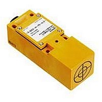
Description
Inductive Proximity Sensor
Manufacturer
Omron
Datasheet
1.TL-YS15MB1US.pdf
(6 pages)
Specifications of TL-YS15MB1US
Sensor Input
Inductive
Sensing Range
15mm
Sensing Range Max
15mm
Sensor Housing
Rectangular
Switch Terminals
Screw
Sensor Output
PNP-NO
Peak Reflow Compatible (260 C)
No
Leaded Process Compatible
No
Rohs Compliant
No


TL-YS
Precautions
When mounting a proximity sensor flush with a metallic panel,
be sure to provide a minimum distance as shown in the table
to prevent the sensor from being effected by metallic objects
other than the target.
To prevent mutual interference, be sure to space the sensors
at a distance greater than that shown in the table below.
Metals with different types of plating effect the detecting
distance of inductive proximity sensors. The table at right
shows reference values for the percentage of the rated
detecting distance that may be expected by type of plating
materials.
OMRON ELECTRONICS LLC
One East Commerce Drive
Schaumburg, IL 60173
1-800-55-OMRON
Cat. No. CEDSAX4
Drawing dimension
A
B
Drawing dimension
C
D
EFFECTS OF SURROUNDING METALS
MUTUAL INTERFERENCE
INFLUENCE OF PLATING
Minimum distance
mm (inch)
150 (5.91)
200 (7.87)
Minimum distance
mm (inch)
45 (1.77)
45 (1.77)
11/01
OMRON ON-LINE
Global - http://www.omron.com
USA - http://www.omron.com/oei
Canada - http://www.omron.com/oci
Specifications subject to change without notice.
Type of plating
Zn
Cr
Ag
Ni
Cu
% of detecting distance (of
standard unplated iron target)
100
75
60
70
70
OMRON CANADA, INC.
885 Milner Avenue
Scarborough, Ontario M1B 5V8
416-286-6465
Printed in the U.S.A.
TL-YS
Related parts for TL-YS15MB1US
Image
Part Number
Description
Manufacturer
Datasheet
Request
R

Part Number:
Description:
PROXIMITY SWITCH, AC
Manufacturer:
Omron
Datasheet:


Part Number:
Description:
AC LSW STYLE,15MM,NC,UNSH
Manufacturer:
Omron
Datasheet:
Part Number:
Description:
Proximity Sensors LSW STYLE 15MM PNP N O UNSH
Manufacturer:
Omron
Datasheet:
Part Number:
Description:
Proximity Sensors AC LSW STYLE 15MM NO Unsh
Manufacturer:
Omron
Datasheet:

Part Number:
Description:
SENSOR PROX SCR-NO 90-250V 15MM
Manufacturer:
Omron
Datasheet:
Part Number:
Description:
Proximity Sensors AC LSW STYLE 15MM NO Unsh
Manufacturer:
Omron
Datasheet:
Part Number:
Description:
Proximity Sensors LSW STYLE 15MM NPN N O UNSH
Manufacturer:
Omron
Datasheet:
Part Number:
Description:
Proximity Sensors LSW STYLE 15MM NPN N O UNSH
Manufacturer:
Omron
Datasheet:
Part Number:
Description:
Proximity Sensors C LSW STYLE 1 5MM S.D.
Manufacturer:
Omron
Datasheet:

Part Number:
Description:
BLOCK PRX,10MM,NPN,NC,UNSH
Manufacturer:
Omron
Datasheet:
Part Number:
Description:
AC,BLOCK PRX,5MM,NO,UNSH
Manufacturer:
Omron
Datasheet:
Part Number:
Description:
AC,FLAT PRX,2MM,NO,SHLD
Manufacturer:
Omron
Datasheet:

Part Number:
Description:
FLAT PROXIMITY
Manufacturer:
Omron
Datasheet:

Part Number:
Description:
MINI FLAT PROX
Manufacturer:
Omron
Datasheet: