T18VP6URQ BANNER ENGINEERING, T18VP6URQ Datasheet - Page 3
T18VP6URQ
Manufacturer Part Number
T18VP6URQ
Description
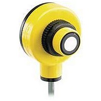
Photoelectric Ultrasonic Sensor
Manufacturer
BANNER ENGINEERING
Type
Ultrasonicr
Specifications of T18VP6URQ
Sensing Range Min
300mm
Sensing Range Max
60cm
Switching Frequency
230kHz
Beam Angle
15°
Operating Temperature Range
-40°C To +70°C
Sensor Input
Ultrasonic
Supply Voltage Max
30VDC
Primary Type
Photoelectric
Sensing Mode
Opposed


Sensing Range
Ultrasonic Frequency
Minimum Spacing
(adjacent pairs)
Supply Voltage
Supply Current
Receiver Output Configuration
Output Rating
Output Protection Circuitry
Delay at Power-up
Output Response Time
Rep Rate
Mechanical Sensing
Repeatability at 300 mm (12")
Range
Beam Angle (-3dB full angle)
Indicators
Construction
Connections
Environmental Rating
Operating Conditions
Vibration and
Mechanical Shock
Certifications
Banner Engineering Corp. • Minneapolis, MN U.S.A
www.bannerengineering.com • Tel: 763.544.3164
Normal Resolution: 600 mm (24")
High Resolution: 300 mm (12")
230 KHz
50 mm for emitter-to-receiver separations of up to 150 mm. Add 10 mm of adjacent pair spacing for every 100 mm
of emitter-to-receiver spacing beyond 150 mm.
12 to 30V dc (10% max. ripple)
50 mA (emitters); 35 mA (receivers), exclusive of output load
NPN (sinking) or PNP (sourcing), depending on model; Normally Open (NO) and Normally Closed (NC)
(complementary)
150 mA max. (each output) at 25°C, derated to 100 mA at 70°C (derate ≈ 1 mA per °C).
Both outputs may be used simultaneously.
ON-state saturation voltage: < 1.5V at 10 mA; < 2.0V at 150 mA
OFF-state leakage current: < 1 microamp at 30V dc
Protected against overload and short circuit conditions. No false pulse upon receiver power-up.
100 milliseconds
Normal Resolution Mode: 2 milliseconds ON and OFF
High Resolution Mode: 1 millisecond ON and OFF
Normal Resolution Mode: 125 Hz max.
High Resolution Mode: 200 Hz max.
Normal Resolution Mode: < 2 mm (< 0.08")
High Resolution Mode: < 1 mm (< 0.04")
15 ± 2°
Emitters have a Green LED for Power ON.
Receivers have one Green Power LED and one Yellow Signal LED.
Green Power LED: ON indicates power on
Yellow Signal LED: sonic signal received (flash rate is proportional to received signal strength; flash is from full to
Patented T-style yellow PBT housing with black PBT back cover. Transducer housing is threaded M18 x 1. Mating
jam nut is supplied for mounting. Acoustic face is epoxy reinforced. Circuitry is epoxy encapsulated.
Emitter: 2 m (6.5') attached PVC-covered 2-wire cable or 4-pin Euro-Style quick disconnect fitting
Receiver: 2 m (6.5') attached PVC-covered 4-wire cable or 4-pin Euro-Style quick disconnect fitting
9 m (30') cables available by request. A model with a QD connector requires a mating cable; see page 4.
NEMA 6P, IEC IP67.
Temperature: -40° to +70°C (-40° to +158° F)
All models meet Mil. Std. 202F requirements method 201A (vibration: 10 to 60 Hz max. double amplitude 0.06",
max. acceleration 10G) and method 213B conditions H & I (Shock: 75G with unit operation: 100G for non-operation)
Also meets IEC 947-5-2; 30G, 11 ms duration, half sine wave.
Flashing indicates output overload
half intensity)
Specifications
US
U-GAGE
®
T18U Series Sensor
P/N 40124 rev. B
3
Related parts for T18VP6URQ
Image
Part Number
Description
Manufacturer
Datasheet
Request
R

Part Number:
Description:
Photoelectric Sensor
Manufacturer:
BANNER ENGINEERING
Datasheet:

Part Number:
Description:
Photoelectric Sensor
Manufacturer:
BANNER ENGINEERING
Datasheet:

Part Number:
Description:
LEDIR70XD4-XM-81039 MAX INTENS STROBE ONLY NO BANNER MARKS
Manufacturer:
BANNER ENGINEERING
Part Number:
Description:
M18SP6DL-72225 LABELED MOELLER NO BANNER MARKINGS BULK PACK
Manufacturer:
BANNER ENGINEERING
Part Number:
Description:
M18SP6DLQ-72226 LABLED MOELLER NO BANNER MARKINGS BULK PACK
Manufacturer:
BANNER ENGINEERING
Part Number:
Description:
M18SP6L-72223 LABELED MOELLER NO BANNER MARKINGS BULK PACK
Manufacturer:
BANNER ENGINEERING
Part Number:
Description:
M18SP6LQ-72224 LABELED MOELLER NO BANNER MARKINGS BULK PACK
Manufacturer:
BANNER ENGINEERING
Part Number:
Description:
P4D1-77908 P4 DRIVER GENERIC NO BANNER MARKINGS RESALE TO CUSTOMER
Manufacturer:
BANNER ENGINEERING
Part Number:
Description:
Photoelectric Sensor
Manufacturer:
BANNER ENGINEERING
Datasheet:

Part Number:
Description:
Programmable Indicator Light
Manufacturer:
BANNER ENGINEERING
Datasheet:
Part Number:
Description:
INDICATOR LED PANEL 50MM GRN/RED/YEL 30V
Manufacturer:
BANNER ENGINEERING
Datasheet:
Part Number:
Description:
Programmable Indicator Light
Manufacturer:
BANNER ENGINEERING
Datasheet: