PTGL09AR390N0B52A0 Murata, PTGL09AR390N0B52A0 Datasheet - Page 83
PTGL09AR390N0B52A0
Manufacturer Part Number
PTGL09AR390N0B52A0
Description
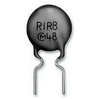
POSISTOR, PTC, CIRCUIT PROTECTION
Manufacturer
Murata
Series
PTGr
Type
PTCr
Datasheet
1.PTGL05AR151H8P52B0.pdf
(84 pages)
Specifications of PTGL09AR390N0B52A0
Thermistor Type
PTC
Resistance
39ohm
Svhc
No SVHC (18-Jun-2010)
Current Max
0.6A
Operating Temperature Max
+85°C
Operating Voltage
250V
Package / Case
Radial
Resistance Tolerance
± 30%
Tolerance
30 %
Termination Style
Radial
Operating Temperature Range
- 10 C to + 60 C
Current Rating
100 mAmps
Dimensions
7.4 mm Dia. x 4 mm H
Lead Spacing
5 mm
Voltage
250 V
Lead Free Status / RoHS Status
Lead free / RoHS Compliant
Lead Free Status / RoHS Status
Lead free / RoHS Compliant


11
!Note
• This PDF catalog is downloaded from the website of Murata Manufacturing co., ltd. Therefore, it’s specifications are subject to change or our products in it may be discontinued without advance notice. Please check with our
• This PDF catalog has only typical specifications because there is no space for detailed specifications. Therefore, please approve our product specifications or transact the approval sheet for product specifications before ordering.
sales representatives or product engineers before ordering.
!Note
82
Lead Type PTGL Series Package
125/250/265V Series Taping Dimensions
Continued from the preceding page.
• Please read rating and !CAUTION (for storage, operating, rating, soldering, mounting and handling) in this catalog to prevent smoking and/or burning, etc.
• This catalog has only typical specifications because there is no space for detailed specifications. Therefore, please approve our product specifications or transact the approval sheet for product specifications before ordering.
Pitch of Component
Pitch of Sprocket Hole
Lead Spacing
Length from Hole Center to Lead
Length from Hole Center to Component Center
Body Diameter
Body Thickness
Deviation along Tape, Left or Right
Carrier Tape Width
Position of Sprocket Hole
Lead Distance between Reference and
Bottom Planes
Protrusion Length
Diameter of Sprocket Hole
Lead Diameter
Total Tape Thickness
Total Thickness of Tape and Lead Wire
Deviation across Tape
Portion to cut in Case of Defect
Hold Down Tape Width
Hold Down Tape Position
Coating Extension on Lead
Item
Code
h
W
1
W
W
H
H
D
P
P
P
W
P
F
D
T
t
t
d
, h
L
e
I
1
2
S
0
1
2
0
2
0
1
0
2
P
P
1
2
2
P
F
0
D
Up to the center of crimp
P
Please see Ratings
Please see Ratings
Dimensions (mm)
W0.5 to Y1.0
d
11.0
11.0 min.
12.7 0.3
3.85 0.8
6.35 1.3
18.0 0.5
16.0 1.0
6.0 max.
0.6 0.05
2.0 max.
1.5 max.
4.0 max.
5.0
9.0
4.0 0.2
0.6 0.3
12.7
S
1.5
+0.8
–0.3
+0.5
–0.75
+0
–2.0
h
T
1
Tolerance is determined by S.
Deviation in the feeding direction
Including the inclination caused by lead bending.
Deviation of tape width.
h
2
Note
R90E.pdf
07.3.19
Related parts for PTGL09AR390N0B52A0
Image
Part Number
Description
Manufacturer
Datasheet
Request
R

Part Number:
Description:
Murata Microblower 20x20 DCDC Driver Board - Samples Only
Manufacturer:
Murata
Part Number:
Description:
357-036-542-201 CARDEDGE 36POS DL .156 BLK LOPRO
Manufacturer:
Murata
Datasheet:
Part Number:
Description:
Manufacturer:
Murata
Datasheet:
Part Number:
Description:
Manufacturer:
Murata
Datasheet:
Part Number:
Description:
Manufacturer:
Murata
Datasheet:
Part Number:
Description:
Manufacturer:
Murata
Datasheet:
Part Number:
Description:
Manufacturer:
Murata
Datasheet:
Part Number:
Description:
Manufacturer:
Murata
Datasheet:
Part Number:
Description:
Manufacturer:
Murata
Datasheet:
Part Number:
Description:
BLM21BD751SN1On-Board Type (DC) EMI Suppression Filters
Manufacturer:
Murata
Datasheet:
Part Number:
Description:
BLM15AG100SN1On-Board Type (DC) EMI Suppression Filters
Manufacturer:
Murata
Datasheet:
Part Number:
Description:
NFE31PT222Z1E9On-Board Type (DC) EMI Suppression Filters
Manufacturer:
Murata
Datasheet:
Part Number:
Description:
Chip Coil
Manufacturer:
Murata
Datasheet:
Part Number:
Description:
Chip Coil
Manufacturer:
Murata
Datasheet: