XF2M-2015-1A Omron, XF2M-2015-1A Datasheet - Page 2
XF2M-2015-1A
Manufacturer Part Number
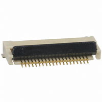
XF2M-2015-1A
Description
CONN FPC 20POS 0.5MM PITCH SMD
Manufacturer
Omron
Series
XF2Mr
Specifications of XF2M-2015-1A
Contact Plating
Gold
Connector Type
Top and Bottom Contacts
Number Of Positions
20
Pitch
0.020" (0.50mm)
Ffc, Fcb Thickness
0.30mm
Height Above Board
0.083" (2.10mm)
Mounting Type
Surface Mount, Right Angle
Cable End Type
Straight
Termination
Solder
Locking Feature
Rotary Lock, Backlock
Contact Finish
Gold
Contact Finish Thickness
5.9µin (0.15µm)
Operating Temperature
-30°C ~ 85°C
Current Rating
0.500A
Voltage Rating
50V
Housing Material
Liquid Crystal Polymer (LCP)
Product Type
PCB
Number Of Positions / Contacts
20
Mounting Angle
Straight
Mounting Style
Through Hole
Contact Material
Spring Copper Alloy / Nickel Substrate
Termination Style
Solder Pin
Gender
Receptacle
Pitch Spacing
0.5mm
No. Of Contacts
20
No. Of Rows
1
Ffc/fpc Thickness
0.3mm
Contact Termination
Surface Mount Vertical
Lead Free Status / RoHS Status
Lead free / RoHS Compliant
Features
-
Lead Free Status / Rohs Status
Lead free / RoHS Compliant
Other names
OR719TR
XF2M20151A
XF2M20151A
Available stocks
Company
Part Number
Manufacturer
Quantity
Price
Company:

Part Number:
XF2M-2015-1A
Manufacturer:
OMRON
Quantity:
12 000
Part Number:
XF2M-2015-1A
Manufacturer:
OMRON/欧姆龙
Quantity:
20 000


Dimensions
Unit: mm
XF2M-@@15-1A
XF2M-@@15-1AH
Table of Dimensions
32
Pins
10
12
14
18
20
22
24
26
30
32
33
34
35
36
38
40
42
45
50
55
60
(3.2) (3.1)
Rotary Backlock Connector (0.5-mm pitch, Dual Contact)
Reference pin mark
FPC insertion dimension
0.5
Model
XF2M-1015-1A
XF2M-1215-1A
XF2M-1415-1A
XF2M-1815-1A
XF2M-2015-1A
XF2M-2215-1A
XF2M-2415-1A
XF2M-2615-1A
XF2M-3015-1A
XF2M-3215-1A
XF2M-3315-1A
XF2M-3415-1A
XF2M-3515-1A
XF2M-3615-1A
XF2M-3815-1A
XF2M-4015-1A
XF2M-4215-1A
XF2M-4515-1A
XF2M-5015-1A
XF2M-5515-1AH
XF2M-6015-1AH
A
C
D
B
E
X
X
*
0.15
*
3.4
1.1
2
A
4.5
5.5
6.5
8.5
9.5
10.5
11.5
12.5
14.5
15.5
16.0
16.5
17.0
17.5
18.5
19.5
20.5
22.0
24.5
27.0
29.5
4.9
* Dotted lines indicate the shape and dimensions
of the XF2M-@@15-1AH connectors.
Cross-section diagram :X-X
2.1
(4.88) *
(4.62)
5.2
(5.9)
(6.2) *
B
5.6
6.6
7.6
9.6
10.6
11.6
12.6
13.6
15.6
16.6
17.1
17.6
18.1
18.6
19.6
20.6
21.6
23.1
25.6
28.1
30.6
1.35 (Effective stacking length)
*
0.92
0.6
*
C
8.5
9.5
10.5
12.5
13.5
14.5
15.5
16.5
18.5
19.5
20.0
20.5
21.0
21.5
22.5
23.5
24.5
26.0
28.5
31.0
33.5
2.1 *
(3.1)
(3.2) *
XF2M
D
9.1
10.1
11.1
13.1
14.1
15.1
16.1
17.1
19.1
20.1
20.6
21.1
21.6
22.1
23.1
24.1
25.1
26.6
29.1
31.6
34.1
(Reinforcement
PCB Mating Dimensions (TOP VIEW)
board)
0.5
4.5
0.35
0.5
2.5MIN
±0.05
0.5
Applicable FPC Dimensions
±0.03
±0.1
±0.05
E
7.1
8.1
9.1
11.1
12.1
13.1
14.1
15.1
17.1
18.1
18.6
19.1
19.6
20.1
21.1
22.1
23.1
24.6
27.1
29.6
32.1
A
(B-0.1)
G
F
±0.05
±0.1
±0.1
A
±0.05
±0.05
F
6.1
7.1
8.1
10.1
11.1
12.1
13.1
14.1
16.1
17.1
17.6
18.1
18.6
19.1
20.1
21.1
22.1
23.6
26.1
28.6
31.1
0.25
R0.1
T=0.3
(Conductive plating)
1.35
(Effective
stacking length)
±0.05
2.6
1.5
±0.05
±0.1
±0.1
1.1
±0.1
G
9.5
10.5
11.5
13.5
14.5
15.5
16.5
17.5
19.5
20.5
21.0
21.5
22.0
22.5
23.5
24.5
25.5
27.0
29.5
32.0
34.5
Related parts for XF2M-2015-1A
Image
Part Number
Description
Manufacturer
Datasheet
Request
R

Part Number:
Description:
CONNECTOR FPC 20POS 0.3MM SMD
Manufacturer:
Omron
Datasheet:

Part Number:
Description:
CONN FPC 30POS 0.5MM PITCH SMD
Manufacturer:
Omron
Datasheet:

Part Number:
Description:
CONN FPC 32POS 0.5MM PITCH SMD
Manufacturer:
Omron
Datasheet:
Part Number:
Description:
CONN FPC 14POS 0.5MM PITCH SMD
Manufacturer:
Omron
Datasheet:

Part Number:
Description:
G6S-2GLow Signal Relay
Manufacturer:
Omron Corporation
Datasheet:
Part Number:
Description:
Compact, Low-cost, SSR Switching 5 to 20 A
Manufacturer:
Omron Corporation
Datasheet:
Part Number:
Description:
Manufacturer:
Omron Corporation
Datasheet:
Part Number:
Description:
Manufacturer:
Omron Corporation
Datasheet:
Part Number:
Description:
Manufacturer:
Omron Corporation
Datasheet:
Part Number:
Description:
Manufacturer:
Omron Corporation
Datasheet: