CCM03-3517 C&K Components, CCM03-3517 Datasheet
CCM03-3517
Specifications of CCM03-3517
CCM03-3517
CCM03-3517TR
CCM03-3517TR
Y115431-3517 01
Available stocks


Related parts for CCM03-3517


CCM03-3517 Summary of contents
Page 1
... ITT - CCM Catalog 11/20/00 12:28 PM Page 29 A new range of CCM03 connectors have been developed to interface with SIM/SAM cards as defined by GSM11- 11 and ENV1375-1. The connectors are available with either hinged covers or fixed covers and have been designed to minimize the amount of space needed for PCB mounting ...
Page 2
... Terminal width = Length = 1.5 mm. (For double reflow). **Note: On request - Depending on quantities. Packaging CCM03 are packaged in accordance with EIA 481-3. Standard packaging is on tape and reel. A modification code is added to the part number that indicates reel packaging and the number of components per reel. There are 5 reels per box. ...
Page 3
... PCB locating pegs) 3003 (8 contacts) 3004 (8 contacts - PCB locating pegs) 3009 (6 contacts - lock with bump) With pegs* Without pegs CCM03-3003 / 3004 1. Mounting pegs only available with CCM03-3002 / 3004 Unless otherwise stated, tolerances are ± 0. Open Dimensions are shown in mm Dimensions subject to change ...
Page 4
... ITT - CCM Catalog 11/20/00 12:28 PM Page 32 Dimensional Drawings Hinged Cover CCM03 - 3005 (6 contacts - with stand off 1.90 mm) Note: Coplanarity of soldering surfaces: ± 0.05 mm PCB Layout CCM03-3005 Open Unless otherwise stated, tolerances are ± 0. Dimensions are shown in mm Dimensions subject to change ...
Page 5
... ITT - CCM Catalog 11/20/00 12:28 PM Page 33 Dimensional Drawings Hinged Cover CCM03 - 3006 (6 contacts - with locating pegs 1.90 mm) Note: Coplanarity of soldering surfaces: ± 0.05 mm PCB Layout CCM03-3006 Unless otherwise stated, tolerances are ± 0. Open Dimensions are shown in mm Dimensions subject to change ...
Page 6
... ITT - CCM Catalog 11/20/00 12:28 PM Page 34 Dimensional Drawings Hinged Cover CCM03 - 3007 (8 contacts - with stand off 1.90 mm) Note: Coplanarity of soldering surfaces: ± 0.05 mm PCB Layout CCM03-3007 Unless otherwise stated, tolerances are ± 0. Open Dimensions are shown in mm Dimensions subject to change ...
Page 7
... ITT - CCM Catalog 11/20/00 12:28 PM Page 35 Dimensional Drawings Note: Coplanarity of soldering surfaces: ± 0.05 mm PCB Layout CCM03-3008 Hinged Cover CCM03-3008 (8 contacts - with locating pegs 1.90 mm) Unless otherwise stated, tolerances are ± 0. Open Dimensions are shown in mm Dimensions subject to change ...
Page 8
... ITT - CCM Catalog 11/20/00 12:28 PM Page 36 Dimensional Drawings Hinged Cover CCM03-3013 (6 contacts + Card Detect Switch) Note: Coplanarity of soldering surfaces: ± 0.05 mm PCB Layout CCM03-3013 Unless otherwise stated, tolerances are ± 0.10 mm Dimensions are shown in mm Dimensions subject to change 34 ...
Page 9
... ITT - CCM Catalog 11/20/00 12:28 PM Page 37 Dimensional Drawings Fixed cover CCM03-3505 (6 contacts not shown) / CCM03-3504 (8 contacts) Note: Coplanarity of soldering surfaces: ± 0.05 mm PCB Layout CCM03-3505 Unless otherwise stated, tolerances are ± 0. CCM03-3504 Dimensions are shown in mm Dimensions subject to change ...
Page 10
... ITT - CCM Catalog 11/20/00 12:28 PM Page 38 Dimensional Drawings PCB Layout CCM03-3512 Hinged Cover CCM03-3512 (6 contacts) Note: Coplanarity of soldering surfaces: ± 0.05 mm Unless otherwise stated, tolerances are ± 0. Dimensions are shown in mm Dimensions subject to change ...
Page 11
... ITT - CCM Catalog 11/20/00 12:28 PM Page 39 Dimensional Drawings Hinged Cover CCM03-3514 (6 contacts - with switch on metal lock) PCB Layout CCM03-3514 Note: Coplanarity of soldering surfaces: ± 0.05 mm Unless otherwise stated, tolerances are ± 0. Dimensions are shown in mm Dimensions subject to change ...
Page 12
... Temperature/time profile acc. to CECC00802 para. 6.1, Fig. 3 with peak temperature 250°C Damp heat IEC 512 test number 11c (10 days) Salt mist IEC 512 test number 11f (96 hours) Ordering Code Part Number N° of Cover Contacts CCM03-3517 6 Hinged CCM03-3518 6 Hinged 38 2 Card Presence Quantity Switch ...
Page 13
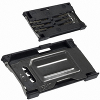
... ITT - CCM Catalog 11/20/00 12:28 PM Page 41 Dimensional Drawings Note: Coplanarity of soldering surfaces: ± 0.05 mm PCB Layout CCM03-3517 Hinged Cover CCM03-3517 (6 contacts) Unless otherwise stated, tolerances are ± 0. OPEN Dimensions are shown in mm Dimensions subject to change ...
Page 14
... ITT - CCM Catalog 11/20/00 12:28 PM Page 42 Dimensional Drawings Note: Coplanarity of soldering surfaces: ± 0.05 mm PCB Layout CCM03-3518 Hinged Cover CCM03-3518 (6 contacts) Unless otherwise stated, tolerances are ± 0. OPEN Dimensions are shown in mm Dimensions subject to change ...
Page 15
... ITT - CCM Catalog 11/20/00 12:28 PM Page 43 Introducing the new CCM03 Series SIM/SAM Card Connector from ITT Cannon Switch Products, featuring an integrated card detection switch. This connector provides a competitive advantage to smart card reader device manufacturers by minimizing the space usage on the PCB, and features a side entry to offer convenient card access without opening the device ...
Page 16
... ITT - CCM Catalog 11/20/00 12:28 PM Page 44 Dimensional Drawings CCM03 – 3753 / 3757 PCB Layout CCM03 – 3752 / 3753 / 3754 CCM03 – 3752 / 3754 / 3758 CCM03 – 3757 / 3758 42 Dimensions are shown in mm Dimensions subject to change ...