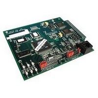
E2 OPTO 22, E2 Datasheet - Page 6

E2
Manufacturer Part Number
E2
Description
Programmable Logic Controller
Manufacturer
OPTO 22
Type
Ethernetr
Datasheet
1.E1.pdf
(10 pages)
Specifications of E2
Peak Reflow Compatible (260 C)
No
Leaded Process Compatible
No
Communication
RS-422/485
Current, Input
0.5 A
Input Type
Analog
Mounting Type
Rack
Number Of Expansion Modules
1
Output Type
Analog
Primary Type
Controller
Terminal Type
Terminal Block
Termination
Terminal Block
Voltage, Supply
5-5.2 VDC
Lead Free Status / RoHS Status
Contains lead / RoHS non-compliant
For Use With
I/O Rack
PAGE
6
Routing Serial Optomux-based Control over an Ethernet Network
Opto 22 • 43044 Business Park Drive • Temecula, CA 92590-3614 • www.opto22.com
SALES 800-321-6786 • 951-695-3000 • FAX 951-695-3095 • sales@opto22.com • SUPPORT 800-835-6786 • 951-695-3080 • FAX 951-695-3017 • support@opto22.com
© 2005–2011 Opto 22. All rights reserved. Dimensions and specifications are subject to change. Brand or product names used herein are trademarks or registered trademarks of their respective companies or organizations.
Host using Optomux over
serial (RS-422/485) link
E2
E2
E1 configured for serial-to-Ethernet routing
E1
E1 and E2 Brain Boards
This diagram shows how an existing
Optomux-based I/O system for an
RS-422/485 serial network can be
migrated to an Ethernet network. In
this system, each original B1 or B2
brain board has been replaced with
an E1 or E2, and all brain boards are
connected to an Ethernet network.
One E1 or E2 brain board is
connected via an RS-422/485 serial
connection to the host PC running
the Optomux application. For each
Optomux command sent from the
PC, this brain board determines
which I/O unit the command must
be sent to and then routes the
command to that unit over the
Ethernet network. I/O point data is
routed from the E1 and E2 brain
boards to the PC in a similar
manner.
Because an Ethernet network is
used, the existing Optomux
application can now monitor and
control E1 and E2 I/O units located
far beyond the reach of the original
RS-422/485 serial network—for
example, in a different building, or
even on another continent.
For more information on using E1
and E2 brain boards in an existing
Optomux I/O system, see the E1 and
E2 Architecture and Migration
Overview (Opto 22 form 1567) and
the E1 and E2 User’s Guide (Opto 22
form 1563).


