F3SNA0457P25 Omron, F3SNA0457P25 Datasheet - Page 15
F3SNA0457P25
Manufacturer Part Number
F3SNA0457P25
Description
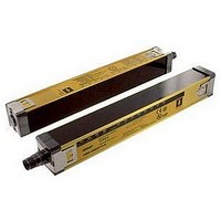
Safety Light Curtain
Manufacturer
Omron
Datasheet
1.F3SN-A0207P14.pdf
(40 pages)
Specifications of F3SNA0457P25
Beam Spacing
15mm
Control Output Type
PNP
No. Of Beams
29
Protection Height
457mm
Sensing Range Max
10m
Supply Voltage Max
24VDC
Peak Reflow Compatible (260 C)
No
Light Curtain Type
Safety
Lead Free Status / RoHS Status
Contains lead / RoHS non-compliant


I/O Circuit Diagrams
Internal Circuit Diagram
Note: The numbers in ❍ indicate pin numbers of the connectors.
*1. Open: normal light emission, short to the +24 VDC: stops light emission
*2. Refer to “Connections”, “Wiring for Sensor Only Configuration” on page 13.
*3. The section encircled with the dashed line is applied for models ending in -01, -03, -04, or -05 only.
Cables with Connector on One End
F39-JC3A (3 m)
F39-JC7A (7 m)
F39-JC10A (10 m)
F39-JC15A (15 m)
External indicator
output
External indicator
output
The numbers in ● indicate pin numbers of the series connection connectors.
Model
Load
Load
0 V
0 V
*3
*3
4
7
8
7
http://www.ia.omron.com/
RS-485(A)
3
4
2
5
8
Gray
Gray
6
1
7
Receiver main
Receiver main
Emitter main
5
5
Display
circuit 2
circuit 1
Display
circuit
6
6
RS-485(B)
Pink
Pink
1
2
3
4
5
6
7
8
Internal wiring
2
3
1
4
7
2
8
3
1
4
7
Brown
Green
White
Yellow
Blue
Brown
Red
Green
White
Yellow
Blue
Auxiliary
output
Test input *1
Interlock selection input *2
Reset input *2
OSSD 1
OSSD 2
EDM input *2
Wire color
Load
White
Brown
Green
Yellow
Gray
Pink
Blue
Red
Load
(c)Copyright OMRON Corporation 2007 All Rights Reserved.
Pin No.
1
2
3
4
5
6
7
8
Load
White
Brown
Green
Yellow
Gray
Pink
Blue
Red
color
Wire
+24 V
0 V
F3SN-A/F3SN-B/F3SH-A
Connector Pins Arrangement
OSSD 2
+24 V
OSSD 1
Auxiliary output
RS-485(A)
RS-485(B)
0 V
EDM input
Receiver
7
6
1
5
8
4
2
3
Signal name
Interlock selection
input
+24 V
Test input
Reset input
RS-485(A)
RS-485(B)
0 V
N.C.
Emitter
15
Related parts for F3SNA0457P25
Image
Part Number
Description
Manufacturer
Datasheet
Request
R

Part Number:
Description:
G6S-2GLow Signal Relay
Manufacturer:
Omron Corporation
Datasheet:
Part Number:
Description:
Compact, Low-cost, SSR Switching 5 to 20 A
Manufacturer:
Omron Corporation
Datasheet:
Part Number:
Description:
Manufacturer:
Omron Corporation
Datasheet:
Part Number:
Description:
Manufacturer:
Omron Corporation
Datasheet:
Part Number:
Description:
Manufacturer:
Omron Corporation
Datasheet:
Part Number:
Description:
Manufacturer:
Omron Corporation
Datasheet:
Part Number:
Description:
Manufacturer:
Omron Corporation
Datasheet:
Part Number:
Description:
Manufacturer:
Omron Corporation
Datasheet: