DMC-20LCD-1-9-C Murata Power Solutions Inc, DMC-20LCD-1-9-C Datasheet - Page 4
DMC-20LCD-1-9-C
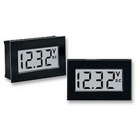
Manufacturer Part Number
DMC-20LCD-1-9-C
Description
DPM, LCD, 3.5DIGIT, 9V
Manufacturer
Murata Power Solutions Inc
Datasheet
1.DMC-20LCD-1-9-C.pdf
(6 pages)
Specifications of DMC-20LCD-1-9-C
Supply Voltage Range
7.5V To 14V
No. Of Digits / Alpha
3.5
Display Size
46.38mm X 32.51mm
Panel Cutout Height
21.3mm
Panel Cutout Width
33.9mm
Operating Temperature Range
0°C To +60°C
Svhc
No SVHC
Lead Free Status / RoHS Status
Lead free / RoHS Compliant


2. Differential Input Configurations: Differential measurements can be
3. Engineering Scaling: For measuring voltages greater than the full
www.cd4power.com
APPLICATIONS
DMS-20LCD Series
made with either 5V-powered or 9V-powered meters. Figure 3, though
not a practical real-world application, uses a voltage divider to demon-
strate the concept of a differential input signal. Be careful not to exceed
the ±2V common mode voltage limitation for 5V powered meters.
scale input range of a given meter, the input signal must be attenuated.
A simple voltage divider (similar to that shown in Figure 4) will scale
the input to within the range of the selected meter. R1 and R2 should
be precision, ±1%, metal-film resistors with absolute TCR’s less than
50ppm/°C. See Ap Note 4 for more information on engineering scaling.
120 VAC
+
120 VAC
–
R1 + R2
V
50kΩ < R1 + R2 < 10MΩ
IN
AC to DC Converter
REF IN
REF OUT
R2
Figure 3. Differential Input Configuration
UPA-5/500
DATEL
R1
R2
DP1
AC to DC Converter
Figure 4. Input Attenuation Circuit
UPA-5/500
DATEL
8
+5V SUP
7
6
x V
(–) IN LO
(+) IN HI
(5V-Powered Models)
IN
11
12
1
= Reading
DMS-20LCD-1-5
+5V SUP
DMS-20LCD-1-5
1
3
5V RET
3
5V RET
11
(+) IN HI
12
(–) IN LO
8
7
REF OUT
REF IN
3 ½ D I G I T , L C D D I S P L A Y D I G I T A L P A N E L V O L T M E T E R S
3 ½ D I G I T , L C D D I S P L A Y D I G I T A L P A N E L V O L T M E T E R S
R1
R2
R3
1k
1k
1k
4. Floating Signal Source Measurements: Floating signals can be
5. Process Control (4-to-20mA) Measurements: In many common
measured using the circuits shown in Figures 5 and 6. Figure 5 uses
a 5V-powered meter. Figure 6 uses a 9V-powered meter. Connecting
pin 10 (ANALOG COMMON) to (–) INPUT LO (pin 12) provides the
reference point for the meter’s input.
A “floating” input is a signal that has no galvanic connection to the
meter’s power supply. In the figures below, the 1.5V battery illustrates a
true floating input.
process-control applications, a 4-to-20mA current loop is used to
transmit information. Because DMS-20LCD meters have such high
input impedance, a simple shunt resistor across the meter’s input can
be used to convert the loop current to a voltage. See Figure 7. The
value of the shunt resistor is a function of the scaling requirements of
the particular application and can be calculated using the following
equation:
CELL
1.5V
120 VAC
CELL
1.5V
–
AC to DC Converter
+
–
UPA-5/500
Figure 5. Floating Input Measurements
Figure 6. Floating Input Measurements
DATEL
ANA COMM
(–) IN LO
(+) IN HI
(–) IN LO
(+) IN HI
(5V-Powered Models)
BATTERY
(9V-Powered Models)
D I G I T A L P A N E L M E T E R S
11
12
+5V SUP
9V
12
11
10
+ BAT
1
1
DMS-20LCD-1-5
DMS-20LCD-1-5
–
MPM_DMS-20LCD_E00
5V RET
3
3
–BAT
DP1
6
DP1
6
7
8
REF OUT
REF IN
8
7
REF OUT
REF IN
Page 4 of 6
Related parts for DMC-20LCD-1-9-C
Image
Part Number
Description
Manufacturer
Datasheet
Request
R

Part Number:
Description:
LCD MODULE 20X2 HI CONT LED
Manufacturer:
Optrex America Inc
Datasheet:
Part Number:
Description:
LCD 20X4 SUPERTWIST HI CONT/BKLT
Manufacturer:
Optrex America Inc
Datasheet:
Part Number:
Description:
LCD MODULE 20X2 CHARACTER
Manufacturer:
Optrex America Inc
Datasheet:
Part Number:
Description:
LCD SUPERTWIST 20X4/ LED BACKLT
Manufacturer:
Optrex America Inc
Datasheet:

Part Number:
Description:
LCD MODULE 20X4 CHARACTER
Manufacturer:
Optrex America Inc
Datasheet:
Part Number:
Description:
LCD MODULE 20X1 CHARACTER
Manufacturer:
Optrex America Inc
Datasheet:
Part Number:
Description:
LCD MODULE 20X4 CHARACTER
Manufacturer:
Optrex America Inc
Datasheet:

Part Number:
Description:
LCD MODULE 20X2 HI CONT LED
Manufacturer:
Optrex America Inc
Datasheet:

Part Number:
Description:
LCD MODULE 20X2 CHARACTER
Manufacturer:
Optrex America Inc

Part Number:
Description:
LCD 20X4 SUPERTWIST HI CONT/BKLT
Manufacturer:
Optrex America Inc

Part Number:
Description:
Transformers 5Vin 5Vout 200mA 4000Vdc 1:1.33 turn
Manufacturer:
Murata Power Solutions Inc
Datasheet:

Part Number:
Description:
POWER SUPPLY
Manufacturer:
Murata Power Solutions Inc
Datasheet:

Part Number:
Description:
DPM LED MINI 2VDC 3.5DIG LP RED
Manufacturer:
Murata Power Solutions Inc
Datasheet:

Part Number:
Description:
CONV DC/DC 1W 5VIN 5VOUT SIP SGL
Manufacturer:
Murata Power Solutions Inc
Datasheet:

Part Number:
Description:
CONV DC/DC 1W 5VIN 3.3V SIP SGL
Manufacturer:
Murata Power Solutions Inc
Datasheet: