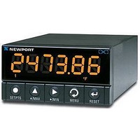
RS24 NEWPORT ELECTRONICS, RS24 Datasheet

RS24
Specifications of RS24
Available stocks
Related parts for RS24
RS24 Summary of contents
Page 1
... NEWPORT Electronics, Inc. ...
Page 2
... NEWPORT Electronics, Inc. ® NEWPORT NEWPORT ® ...
Page 3
...
Page 4
...
Page 5
...
Page 6
...
Page 7
...
Page 8
...
Page 9
...
Page 10
...
Page 11
RJ- RJ- D25 ...
Page 12
METER #30 METER #31 RX/TX TX/RX RO METER #1 HOST COMPUTER RX/ DTE TX/RX ...
Page 13
METER #30 METER # TWISTED SHIELDED PAIR METER #1 RX/TX RECEIVE TRANSMIT HOST COMPUTER DTE B TRANSMIT A B RECEIVE A ...
Page 14
...
Page 15
...
Page 16
...
Page 17
...
Page 18
...
Page 19
...
Page 20
...
Page 21
SPACE (0) MARK (1) LSB START BIT 7-BIT ASCII CHARACTER STOP MSB BIT(S) PARITY (missing if no parity) ...
Page 22
...
Page 23
...
Page 24
...
Page 25
...
Page 26
...
Page 27
...
Page 28
...
Page 29
...
Page 30
...
Page 31
...
Page 32
(continued next page) ...
Page 33
...
Page 34
...
Page 35
...
Page 36
...
Page 37
...
Page 38
...
Page 39
...
Page 40
...
Page 41
...
Page 42
...
Page 43
...
Page 44
...
Page 45
...
Page 46
...
Page 47
...
Page 48
...
Page 49
...
Page 50
...
Page 51
...
Page 52
...
Page 53
...
Page 54
...
Page 55
...
Page 56
...
Page 57
...
Page 58
...
Page 59
...
Page 60
...
Page 61
...
Page 62
...
Page 63
...
Page 64
...
Page 65
...
Page 66
...
Page 67
...
Page 68
...
Page 69
...
Page 70
...
Page 71
...
Page 72
MP.SC.OF MP.SC.OF MP.SC.OF MP.SC.OF MP.SC.OF MP.SC.OF MP.SC.OF MP.SC.OF MP.SC.OF MP.SC.OF ...
Page 73
...
Page 74
...
Page 75
...
Page 76
...
Page 77
...
Page 78
...
Page 79
...
Page 80
ModBus Communication Option Supplement Note: To Enable the MODBUS PROTOCOL via Front LED Display Panel Push Button Menu, enter MOdbUS submenu and select option “yES” in the “COMM” Communication Configuration Menu. 1. Introduction Modbus protocol defines a message structure that ...
Page 81
The Modbus Message frame is shown below DEVICE ADDRESS FUNCTION CODE 8 BITS hh where: • h (hex. Number) – character, • k – integers depend on the contents of the data format. Device Address Code • The address message ...
Page 82
Data Field The data field is constructed using sets of two hexadecimal digits, in the range hexadecimal. The data field of messages sent from a master to slave devices contains additional information, which the slave ...
Page 83
Modbus RTU Registers • The table below shows the Modbus registers supported by the Universal Input Meters: FUNCTION REGISTER CODE 03/04 SP1: SETPOINT 1 VALUE 03/04 SP2: SETPOINT 2 VALUE 03/04 SP3: SETPOINT ...
Page 84
Command Format The following formats are used to SEND commands by computer and RETURNED by device. 8.1. Read Multiple Register (03 or 04) Send to device Command string format: DEVICE FUNCTION CODE ADDRESS 1 BYTE 1 ...
Page 85
Note: the Universal Input Meters support only Read Single Register, so the number of registers should always set to 1. Screenshot for following examples 1- 3: Figure 8.1: Read Command Samples via Infinity Configuration Software. Example 1: For one byte ...
Page 86
Example 2: For 2 bytes data registers: as shown on the Figure 8 the Command sent section 0022 0001 2400 read the value of Alarm Deadband (AL.db). FUNCTION DEVICE CODE ADDRESS ...
Page 87
Example 3: For 3 bytes data registers: as shown on the Figure 8 the Command sent section 0001 0001 D5CA read Setpoint 1 value (SP1). FUNCTION DEVICE CODE ADDRESS ...
Page 88
NOTE: Following bits patterns is the format for 3 bytes data registers of READING SCALE (“RdG.SC”), INPUT SCALE (“INP.SC”), AND OUTPUT SCALE (“Out.SC”) which are determined differently than the above example. Value Format Hex. 00 Pattern XXXX Binary bits N/A ...
Page 89
Example 4: For Write Command of one byte data registers: using example on Section & Table 10.1 of Serial Communication Option Operator’s manual to learn how to modify Reading configuration (RdG.CNF), sent/responded data string as following: FUNCTION DEVICE CODE ADDRESS ...
Page 90
Example 5: For Write Command of two bytes data registers: There are only two registers in this format: Setpoint Deadband (SP.db): Register #21 and Alarm Deadband (AL.db) Register #22. Using Example on Section 10.36 of Serial Communication Option Operator’s manual ...
Page 91
Example 6: For Write Command of three bytes data registers: In order to modify or configure, users must send two write commands to accomplish this task. First one only change register’s 2 Low Order Bytes (LB)and is just similar to ...
Page 92
Value -100: Desired DEVICE Values: ADDRESS -100 st 1 command 1 BYTE (for absolute 01 value command 1 BYTE (for Sign & 01 dec. point) Figure 8.5: Write (3 Data bytes) Commands Sample via 8 Diagnostic command. This ...
Page 93
Warranty/Disclaimer Return Requests/Inquiries ...
Page 94
® ...


