S0161220120-FBC Murata Power Solutions Inc, S0161220120-FBC Datasheet

DC/DC 16A 12V To 1.2-5.0V Adjust

S0161220120-FBC

Manufacturer Part Number
S0161220120-FBC
Description
DC/DC 16A 12V To 1.2-5.0V Adjust
Manufacturer
Murata Power Solutions Inc
Datasheet

Specifications of S0161220120-FBC

Output Power
19 W
Input Voltage Range
10.8 V to 12.6 V
Input Voltage (nominal)
12 V
Number Of Outputs
1
Output Voltage (channel 1)
1.2 V
Output Current (channel 1)
16 A
Package / Case Size
SIP
Output Voltage
1.2 V
Lead Free Status / RoHS Status
Lead free / RoHS Compliant
www.murata-ps.com
www.murata-ps.com
This unit is not fuse protected. User is responsible for providing system protection.
Consult factory for application
* All specifications are typical at nominal input, full load at 25°C unless otherwise stated.
** Pull below 0.35V to disable the SIP; pull above 2.4V (do not exceed 5.5V) to enable the SIP.
*** The output capacitors must meet the max ESR <12 m
Features
Back Bias Protection
Short Circuit Protection
MTBF 4.2 million hours
Can sink 8A current, maintaining Output Regulation
Output Current up to 16A or 45W max
12V +5/-10% input
Load Regulation ±0.5%
Factory set to 1.2V Output with Output Trim up to 5.0V
High Efficiency to 90%
Specifications *
Input Specifications
Input voltage range
External input capacitor
Output Specifications
Standard output voltages
and output current
Load regulation
Line regulation
External output capacitor
Short circuit protection
General Specifications
Enable **
Efficiency
Isolation
Switching frequency
Approvals and Standards
Protection
Operating Temperature ***
Storage Temperature
Weight
MTBF
820μF OSCON or equiv-
200% of maximum rated
alent with ESR < 12m
Input capacitor capable
ON-high / OFF-low
3.6 million hours
of ripple current
information.
12.0V +5/-10%
-40°C to 70°C
10°C to 50°C
Non-isolated
90% - 69%
1.25V, 16A
1.2V, 16A
1.5V, 16A
1.8V, 16A
2.5V, 13A
3.3V, 11A
UL 94V-0
S016-12
5.0V, 9A
360kHz
0.25 oz
current
Fusing
±0.5%
±0.4%
requirement over the operating temperature range.
Per RAC PRISM at 50°C ambient and 300 LFM
Measured at +Vin pin
See ripple current curve on pg 6 and Input and Output
Capacitance table on pg 8
Regulation range is ± 3% including output voltage set
point, line regulation and load regulation over the operat-
ing temperature range.
See DC Voltage Regulation table on pg 6 for trimming to
different voltages
0 to 16A load
12.0V input voltage range
See also Input and Output Capacitance table on pg 8
Autorecovery
See efficiency curves on pg 4
Fixed
Unit is not fused.
See also derating curves
Non-condensing
NOT RECOMMENDED
FOR NEW DESIGNS
12V Input, 1.2 - 5.0V Adjustable Output, 16A or 45W
29 Apr 2010 MDC_S016_084-S016-00.B01 Page 1 of 9
S016_084-S016-00
email: sales@murata-ps.com

Related parts for S0161220120-FBC

S0161220120-FBC Summary of contents

Page 1

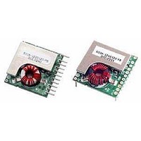
Features Output Current up to 16A or 45W max 12V +5/-10% input Load Regulation ±0.5% Factory set to 1.2V Output with Output Trim up to 5.0V High Efficiency to 90% Back Bias Protection Short Circuit Protection MTBF 4.2 million ...

Page 2

Ordering Information Model Number Input Voltage 12 = 12V Mechanical Options 2 = Vertical Top Side pins (Standard Horizontal Bottom Side Pins Pin Assignments CONNECTOR J1 Set Point Resistor Table Ambient conditions: 400 LFM and 50°C Output Set ...

Page 3

Outline Drawings Vertical Mount Option (S016-1220120-FB) Horizontal Mount Option (S016-1240120-FB www.murata-ps.com .100 ± .020 13 11 S016_084-S016-00 12V Input, 1.2 - 5.0V Adjustable Output, 16A or 45W 1. Dimensions are in inches and (millimeters). 2. Tolerances: (unless otherwise ...

Page 4

Efficiency Curves at 25°C 92.00% 89.00% 86.00% 83.00% 80.00% 77.00% 74.00% 71.00% 68.00% LOAD % 1.2 25% 76.66% 50% 78.04% 75% 74.04% 100% 69.58% Derating Curves Derating Curves 14.00 12.00 10.00 8.00 6.00 4.00 2.00 0.00 20.00 40.00 60.00 80.00 ...

Page 5

PWRGD - Power Good Signal The power good signal will be asserted, driven high, by the converter to indicate that the output is valid. If the output fails the specified DC voltage regulation limits or the output is below 90% ...

Page 6

DC Voltage Regulation The DC output voltages will remain within the regulation ranges shown in the following table when measured at the load end of the connector. Connect Set Resistor per table below from Trim (Pin4) to Ground (Pin7). Regulation ...

Page 7

Output Ripple and Noise The following output ripple/noise requirements will be met throughout the load ranges specified and under all input voltage conditions specified. Ripple and noise are defined as periodic or random signals over the frequency band of 10Hz ...

Page 8

Input and Output Capacitance The power supply requires the following capacitance (or equivalent) on the PWB. Output Level +5V +3.3V +2.5V +1.8V +1.5 1.25V 1.2V * Input Ceramic Capacitance > 4.7μF located close to the module ** Output Ceramic Capacitance ...

Page 9

Shock and Vibration Vibration Test Tri-axis random vibration (as generated by pneumatic hammer) Typical vibration conditions: Frequency Range: Vibration Levels: Step Dwell Time: Final Dwell Time: Unit Line Condition: Unit Load Condition: The UUT will survive any specified vibration level ...

Related keywords