UVQ-12/10-D48P-C Murata Power Solutions Inc, UVQ-12/10-D48P-C Datasheet - Page 12
UVQ-12/10-D48P-C
Manufacturer Part Number
UVQ-12/10-D48P-C
Description
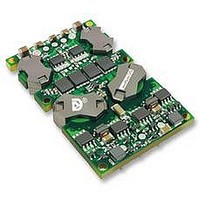
DC/DC TH 10A 48-12V Q-Brick
Manufacturer
Murata Power Solutions Inc
Series
UVQr
Datasheet
1.UVQ-1210-D48P-C.pdf
(20 pages)
Specifications of UVQ-12/10-D48P-C
Dc / Dc Converter O/p Type
Single
No. Of Outputs
1
Input Voltage
36V To 75V
Power Rating
120W
Output Voltage
12V
Output Current
10A
Approval Bodies
EN / IEC / UL
Supply Voltage
48V
Rohs Compliant
Yes
Product
Isolated
Output Power
120 W
Input Voltage Range
36 V ot 75 V
Input Voltage (nominal)
48 V
Number Of Outputs
1
Output Voltage (channel 1)
12 V
Output Current (channel 1)
10 A
Isolation Voltage
2.25 KV
Package / Case Size
Quarter Brick
Lead Free Status / Rohs Status
Details


Thermal Shutdown
UVQ converters are equipped with thermal-shutdown circuitry. If the internal
temperature of the DC/DC converter rises above the designed operating tem-
perature (See Performance Specifi cations), a precision temperature sensor
will power down the unit. When the internal temperature decreases below
the threshold of the temperature sensor, the unit will self start.
Output Overvoltage Protection
The output voltage is monitored for an overvoltage condition via magnetic
coupling to the primary side. If the output voltage rises to a fault condition,
which could be damaging to the load circuitry (see Performance Specifi ca-
tions), the sensing circuitry will power down the PWM controller causing the
output voltage to decrease. Following a time-out period the PWM will restart,
causing the output voltage to ramp to its appropriate value. If the fault condi-
tion persists, and the output voltages again climb to excessive levels, the
overvoltage circuitry will initiate another shutdown cycle. This on/off cycling
is referred to as "hiccup" mode.
Input Reverse-Polarity Protection
If the input-voltage polarity is accidentally reversed, an internal diode will
become forward biased and likely draw excessive current from the power
source. If the source is not current limited or the circuit appropriately fused, it
could cause permanent damage to the converter.
Input Fusing
Certain applications and/or safety agencies may require the installation of
fuses at the inputs of power conversion components. Fuses should also be
used if the possibility of a sustained, non-current-limited, input-voltage polar-
ity reversal exists. For DATEL UVQ Series DC/DC Converters, slow-blow fuses
are recommended with values no greater than twice the maximum input
current.
Trimming Output Voltage
UVQ converters have a trim capability (pin 6) that enables users to adjust the
output voltage from +10% to –20% (refer to the trim equations). Adjustments
to the output voltage can be accomplished with a single fi xed resistor as
shown in Figures 5 and 6. A single fi xed resistor can increase or decrease the
output voltage depending on its connection. Resistors should be located close
to the converter and have TCR's less than 100ppm/°C to minimize sensitivity
to changes in temperature. If the trim function is not used, leave the trim pin
open.
Standard UVQ's have a "positive trim" where a single resistor connected
from the Trim pin (pin 6) to the +Sense (pin 7) will increase the output volt-
age. A resistor connected from the Trim Pin (pin 6) to the –Sense (pin 5) will
decrease the output voltage.
Trim adjustments greater than the specifi ed +10%/–20% can have an
adverse affect on the converter’s performance and are not recommended.
Excessive voltage differences between V
trim adjustment of the output voltage, can cause the overvoltage protection
circuitry to activate (see Performance Specifi cations for overvoltage limits).
www.cd4power.com
®
OUT
and Sense, in conjunction with
Low-Profi le, Isolated Quarter-Brick 2.5-40 Amp DC/DC Converters
Temperature/power derating is based on maximum output current and volt-
age at the converter's output pins. Use of the trim and sense functions can
cause output voltages to increase, thereby increasing output power beyond
the UVQ's specifi ed rating, or cause output voltages to climb into the output
overvoltage region. Therefore:
The Trim pin (pin 6) is a relatively high impedance node that can be suscepti-
ble to noise pickup when connected to long conductors in noisy environments.
In such cases, a 0.22μF capacitor to –Output can be added to reduce this long
lead effect.
Figure 5. Trim Connections To Increase Output Voltages Using Fixed Resistors
Figure 6. Trim Connections To Decrease Output Voltages Using Fixed Resistors
(V
1
2
3
OUT
at pins) x (I
–INPUT
ON/OFF
CONTROL
+INPUT
OUT
) ≤ rated output power
+OUTPUT
–OUTPUT
+SENSE
–SENSE
TRIM
8
7
6
5
4
R
TRIM DOWN
UVQ Series
UVQ Series
LOAD
Page 12 of 20
Related parts for UVQ-12/10-D48P-C
Image
Part Number
Description
Manufacturer
Datasheet
Request
R

Part Number:
Description:
DC/DC Converters & Regulators 120W 48V to 12V 10A NEGATIVE POLARITY
Manufacturer:
Murata Power Solutions Inc
Datasheet:
Part Number:
Description:
DC/DC TH 10A 48-12V Q-Brick
Manufacturer:
Murata Power Solutions Inc
Datasheet:
Part Number:
Description:
DC/DC TH 10A 48-12V Q-Brick
Manufacturer:
Murata Power Solutions Inc
Datasheet:
Part Number:
Description:
DC/DC Converters & Regulators 96W 24V to 12V 8A POS POL BASEPLATE
Manufacturer:
Murata Power Solutions Inc
Datasheet:

Part Number:
Description:
DC/DC Converter
Manufacturer:
Murata Power Solutions Inc
Datasheet:

Part Number:
Description:
DC/DC TH 8A 24-12V Q-Brick
Manufacturer:
Murata Power Solutions Inc
Part Number:
Description:
DC/DC TH 8A 24-12V Q-Brick
Manufacturer:
Murata Power Solutions Inc

Part Number:
Description:
POWER OVER ETHERNET MODULE
Manufacturer:
Murata Power Solutions Inc
Datasheet:

Part Number:
Description:
POWER OVER ETHERNET MODULE
Manufacturer:
Murata Power Solutions Inc
Datasheet:

Part Number:
Description:
Transformers 5Vin 5Vout 200mA 4000Vdc 1:1.33 turn
Manufacturer:
Murata Power Solutions Inc
Datasheet:
Part Number:
Description:
POWER SUPPLY
Manufacturer:
Murata Power Solutions Inc
Datasheet:

Part Number:
Description:
DPM LED MINI 2VDC 3.5DIG LP RED
Manufacturer:
Murata Power Solutions Inc
Datasheet:

Part Number:
Description:
CONV DC/DC 1W 5VIN 5VOUT SIP SGL
Manufacturer:
Murata Power Solutions Inc
Datasheet:

Part Number:
Description:
CONV DC/DC 1W 5VIN 3.3V SIP SGL
Manufacturer:
Murata Power Solutions Inc
Datasheet: