UWR-12/1250-D12AT-C Murata Power Solutions Inc, UWR-12/1250-D12AT-C Datasheet - Page 3
UWR-12/1250-D12AT-C
Manufacturer Part Number
UWR-12/1250-D12AT-C
Description
DC/DC TH 1.25A 12-12V Single A
Manufacturer
Murata Power Solutions Inc
Series
UWRr
Datasheet
1.UWR-3.34250-D48A-C.pdf
(12 pages)
Specifications of UWR-12/1250-D12AT-C
Product
Isolated
Output Power
15 W
Input Voltage Range
10 V to 18 V
Number Of Outputs
1
Output Voltage (channel 1)
12 V
Output Current (channel 1)
1.25 A
Isolation Voltage
1.5 KV
Lead Free Status / Rohs Status
Lead free / RoHS Compliant


Performance/Functional Specifi cations
Typical @ T
Input Voltage Range:
Overvoltage Shutdown:
Start-Up Threshold: ➂
Undervoltage Shutdown: ➂
Input Current:
Input Filter Type
Reverse-Polarity Protection
On/Off Control (Optional, Pin 3): ➃ ➄
V
Minimum Loading for Specifi cation: ➁
Minimum Loading for Stability: ➁
Ripple/Noise (20MHz BW) ➀ ➅
Line/Load Regulation
Effi ciency
Isolation Voltage:
Isolation Capacitance
Isolation Resistance
Current Limiting:
Overvoltage Protection
Temperature Coeffi cient
Transient Response (50% load step)
Start-Up Time: ➂
OUT
D12A Models
D24A Models
D48A Models
D12A Models
D24A Models
D48A Models
D12A Models
D24A Models
D48A Models
D12A Models
D24A Models
D48A Models
Normal Operating Conditions
Standby Mode (Off, OV, UV)
D12AC, D24AC, & D48AC Models
D12AN, D24AN, & D48AN Models
1.2V/1.5V/1.8V/2.5V/3.3V/5V Outputs No load
12V/15V Outputs
1.2V/1.5V/1.8V/2.5V/3.3V/5V Outputs No load
12V/15V Outputs
Input-to-Output
1.2V-5V Outputs
12V and 15V Outputs
1.2V-2.5V models
3.3V-15V models
V
On/Off to V
IN
Accuracy (50% load):
to V
A
= +25°C under nominal line voltage and full-load conditions, unless noted.
OUT
OUT
Dynamic Characteristics
Output
Input
10-18 Volts (12V nominal)
18-36 Volts (24V nominal)
36-75 Volts (48V nominal)
18.5-21 Volts (20V typical)
37-41 Volts (38V typical)
77-81 Volts (78.5V typical)
9.4-10 Volts (9.6V typical)
16.5-18 Volts (17V typical)
34-36 Volts (35V typical)
7-8.5 Volts (8V typical)
15.5-17.5 Volts (16.5V typical)
32.5-35.5 Volts (34V typical)
See Ordering Guide
5mA
Pi
Brief duration, 10A maximum
On = open or 13V to +V
Off = 0-0.8V, I
On = 0-0.8V, I
Off = open or 3.3-5.5V, I
±1.5% (±2% for model UWR-1.2/6000)
10% of I
25mA
See Ordering Guide
See Ordering Guide
See Ordering Guide
1500Vdc minimum (functional)
470pF
100M:
Hiccup technique, auto-recovery
Power-limiting technique, auto-recovery
Zener/transorb clamp, magnetic feedback
±0.04% per °C
200μsec max. to ±2% of fi nal value
200μsec max. to ±1.5% of fi nal value
50msec
30msec
OUT
max.
IN
IN
= 3-12mA typ.
= 3-12mA typ.
IN
IN
, I
= 1-5mA typ.
IN
= 1-5mA typ.
www.murata-ps.com
➀➁
➀ All models are specifi ed with two external 0.47μF multi-layer ceramic capacitors installed across
➁ See Minimum Output Loading Requirements under Technical Notes.
➂ See Technical Notes for details.
➃ The On/Off Control and Trim functions are optional and must be installed by MPS. See Optional
➄ The On/Off Control is designed to be driven with open-collector logic or the application of appro-
➅ Output noise maybe further reduced with the addition of additional external output capacitors.
➆ Operating temperature range without derating is model and input-voltage dependent. See
➇ RoHS-6 hazardous substance compliance does not claim EU RoHS exemption 7b (lead in solder).
Switching Frequency
Operating Temperature (Ambient):
(See Derating Curves)
Case Temperature:
Storage Temperature
Dimensions
Shielding
Case Material
Pin Material
Weight
Input Voltage:
Input Reverse-Polarity Protection
Output Overvoltage Protection:
Output Current
Case Temperature
Storage Temperature
Lead Temperature
These are stress ratings. Exposure of devices to greater than any of these conditions may
adversely affect long-term reliability. Proper operation under conditions other than those
listed in the Performance/Functional Specifi cations Table is not implied.
1.2V models
1.5V D48 models
1.8V D12 models
1.8V D24 models
1.8V D48 models
2.5 and 1.5 D12/D24 models
3.3-12V models
Maximum Allowable
their output pins.
Functions or contact MPS for details.
priate voltages (referenced to –Input, pin 2). Applying a voltage to the On/Off Control pin when
no input voltage is applied to the converter may cause permanent damage. See Technical Notes.
See Technical Notes.
Temperature Derating.
Continuous:
Transient (100msec):
1.2V/1.5/1.8V Outputs
2.5V/3.3V Outputs
5V/12V/15V Outputs
D12 Models
D24 Models
D48 Models
D12 Models
D24 Models
D48 Models
Dynamic Characteristics (continued)
Absolute Maximum Ratings
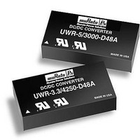
6 Amp/15 Watt DC/DC Converters
05 Apr 2011 MDC_UWR_7-15.F10 Page 3 of 12
Environmental
Physical
22 Volts
44 Volts
88 Volts
50 Volts
50 Volts
100 Volts
Current must be <10 Amps. Brief duration
only. Fusing recommended.
2.1/2.2/2.3 Volts, unlimited duration
TBD/3.4/4.4 Volts, unlimited duration
7.1/16/18 Volts, unlimited duration
Current limited. Devices can withstand sus-
tained output short circuits without damage.
+100°C
–40 to +105°C
See soldering guidelines
250-300kHz ±30kHz, model dependent
260kHz (±30kHz)
280kHz (±30kHz)
250kHz (±30kHz)
210kHz (±20kHz)
340kHz (±40kHz)
310-345kHz ±10%, model dependent
–40 to +85°C with Derating
+100°C
–40 to +105°C
2" x 1" x 0.475" (51 x 25 x 12.1mm)
None
Diallyl phthalate, UL94V-0 rated
Gold-plated copper alloy with nickel underplate
1.4 ounces (39.7 grams)
Single Output, High-Density,
UWR Models
email: sales@murata-ps.com
Related parts for UWR-12/1250-D12AT-C
Image
Part Number
Description
Manufacturer
Datasheet
Request
R

Part Number:
Description:
DC/DC Converters & Regulators 15W 5V to 12V 1.25A
Manufacturer:
Murata Power Solutions Inc
Datasheet:

Part Number:
Description:
Module DC-DC 1-OUT 12V 1.25A 15W 6-Pin Case C14
Manufacturer:
Murata Power Solutions Inc
Datasheet:

Part Number:
Description:
CONV DC/DC 12V 1250MA SINGLE A
Manufacturer:
Murata Power Solutions Inc
Datasheet:
Part Number:
Description:
DC/DC TH 20W 5-12V Single A
Manufacturer:
Murata Power Solutions Inc
Datasheet:
Part Number:
Description:
CONV DC/DC 12V 1250MA SINGLE A
Manufacturer:
Murata Power Solutions Inc
Datasheet:

Part Number:
Description:
DC/DC Converter
Manufacturer:
Murata Power Solutions Inc
Datasheet:

Part Number:
Description:
DC/DC TH 1.25A 12-12V Single A
Manufacturer:
Murata Power Solutions Inc
Datasheet:
Part Number:
Description:
DC/DC TH 1.25A 12-12V Single A
Manufacturer:
Murata Power Solutions Inc
Datasheet:
Part Number:
Description:
DC/DC TH 1.25A 12-12V Single A
Manufacturer:
Murata Power Solutions Inc
Part Number:
Description:
DC/DC TH 1.25A 24-12V Single A
Manufacturer:
Murata Power Solutions Inc
Datasheet:

Part Number:
Description:
DC/DC Converters & Regulators 3W 48V to 5V 500mA
Manufacturer:
Murata Power Solutions Inc
Datasheet:
Part Number:
Description:
DC/DC Converters & Regulators 3W 12V to 5V 500mA
Manufacturer:
Murata Power Solutions Inc
Datasheet:
Part Number:
Description:
CONV DC/DC 12V 1250MA SINGLE A
Manufacturer:
Murata Power Solutions Inc
Datasheet:
Part Number:
Description:
CONV DC/DC 5V 1800MA SGL A T/H
Manufacturer:
Murata Power Solutions Inc
Datasheet:
Part Number:
Description:
CONV DC/DC 5V 4000MA SINGLE A
Manufacturer:
Murata Power Solutions Inc
Datasheet: