UQQ-5/17-Q12P-C Murata Power Solutions Inc, UQQ-5/17-Q12P-C Datasheet - Page 14
UQQ-5/17-Q12P-C
Manufacturer Part Number
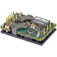
UQQ-5/17-Q12P-C
Description
DC/DC Converter
Manufacturer
Murata Power Solutions Inc
Datasheet
1.UQQ-128-Q12PB-C.pdf
(18 pages)
Specifications of UQQ-5/17-Q12P-C
Dc / Dc Converter O/p Type
Fixed
No. Of Outputs
1
Input Voltage
9V To 36V
Power Rating
85W
Output Voltage
5V
Output Current
17A
Supply Voltage
12V
Dc / Dc Converter Case Style
Quarter Brick
Lead Free Status / RoHS Status
Lead free / RoHS Compliant


Start-Up Threshold and Undervoltage Shutdown
Under normal start-up conditions, the UQQ Series will not begin to regulate
properly until the ramping input voltage exceeds the Start-Up Threshold.
Once operating, devices will turn off when the applied voltage drops below
the Undervoltage Shutdown point. Devices will remain off as long as the
undervoltage condition continues. Units will automatically re-start when
the applied voltage is brought back above the Start-Up Threshold. The
hysteresis built into this function avoids an indeterminate on/off condition
at a single input voltage. See Performance/Functional Specifi cations table for
actual limits.
Start-Up Time
The V
a ramping input voltage crosses the Start-Up Threshold voltage and the
point at which the fully loaded output voltage enters and remains within its
specifi ed accuracy band. Actual measured times will vary with input source
impedance, external input capacitance, and the slew rate and fi nal value of
the input voltage as it appears to the converter. The On/Off to V
time assumes that the converter is turned off via the Remote On/Off Control
with the nominal input voltage already applied.
On/Off Control
The primary-side, Remote On/Off Control function (pin 2) can be specifi ed
to operate with either positive or negative polarity. Positive-polarity devices
("P" suffi x) are enabled when pin 2 is left open or is pulled high. Positive-
polarity devices are disabled when pin 2 is pulled low or left open (with
respect to –Input). Negative-polarity devices are off when pin 2 is high and
on when pin 2 is pulled low or grounded. See Figure 4.
Dynamic control of the remote on/off function is best accomplished with
a mechanical relay or an open-collector/open-drain drive circuit (optically
isolated if appropriate). The drive circuit should be able to sink appropriate
current (see Performance Specifi cations) when activated and withstand
appropriate voltage when deactivated.
Sense Input
Note: The sense and V
resistors. Nevertheless, if sense is not used for remote regulation, the user
must connect + sense to + V
Sense is intended to correct small output accuracy errors caused by the
resistive ohmic drop in output wiring as output current increases. This output
drop (the difference between Sense and V
IN
to V
OUT
Start-Up Time is the interval between the point at which
Figure 4. Driving the Remote On/Off Control Pin
OUT
lines are internally connected through low-value
OUT
and -sense to -V
OUT
when measured at the converter)
OUT
at the converter pins.
OUT
www.murata-ps.com
start-up
should not be allowed to exceed 0.5V. Consider using heavier wire if this
drop is excessive.
Sense is connected at the load and corrects for resistive errors only. Be
careful where it is connected. Any long, distributed wiring and/or signifi cant
inductance introduced into the Sense control loop can adversely affect
overall system stability. If in doubt, test the application, and observe the
DC/DC’s output transient response during step loads. There should be no
appreciable ringing or oscillation. You may also adjust the output trim slightly
to compensate for voltage loss in any external fi lter elements. Do not exceed
maximum power ratings.
Current Limiting
When power demands from the output falls within the current limit incep-
tion range for the rated output current, the DC/DC converter will go into
a current limiting mode. In this condition the output voltage will decrease
proportionately with increases in output current, thereby maintaining a
somewhat constant power dissipation. This is commonly referred to as
power limiting. Current limit inception is defi ned as the point where the full-
power output voltage falls below the specifi ed tolerance. If the load current
being drawn from the converter is signifi cant enough, the unit will go into a
short circuit condition. See “Short Circuit Condition.”
Short Circuit Condition
When a converter is in current limit mode the output voltages will drop as
the output current demand increases. If the output voltage drops too low,
the magnetically coupled voltage used to develop primary side voltages will
also drop, thereby shutting down the PWM controller. Following a time-out
period of about 50 milliseconds, the PWM will restart, causing the output volt-
ages to begin ramping to their appropriate values. If the short-circuit condi-
tion persists, another shutdown cycle will be initiated. This on/off cycling
is referred to as “hiccup” mode. The hiccup cycling reduces the average
output current, thereby preventing internal temperatures from rising to
excessive levels. The UQQ is capable of enduring an indefi nite short circuit
output condition.
Thermal Shutdown
UQQ converters are equipped with thermal-shutdown circuitry. If the inter-
nal temperature of the DC/DC converter rises above the designed operating
temperature (See Performance Specifi cations), a precision temperature
sensor will power down the unit. When the internal temperature decreases
below the threshold of the temperature sensor, the unit will self start.
Output Overvoltage Protection
The output voltage is monitored for an overvoltage condition via magnetic
coupling to the primary side. If the output voltage rises to a fault condition,
which could be damaging to the load circuitry (see Performance Specifi ca-
tions), the sensing circuitry will power down the PWM controller causing
the output voltage to decrease. Following a time-out period the PWM will
restart, causing the output voltage to ramp to its appropriate value. If the
fault condition persists, and the output voltages again climb to excessive
levels, the overvoltage circuitry will initiate another shutdown cycle. This
on/off cycling is referred to as “hiccup” mode.
Wide Input Range Single Output DC/DC Converters
25 Mar 2011 MDC_UQQ.B01 Page 14 of 18
email: sales@murata-ps.com
UQQ Series
Related parts for UQQ-5/17-Q12P-C
Image
Part Number
Description
Manufacturer
Datasheet
Request
R

Part Number:
Description:
CONV DC/DC 85W 17A 5V T/H
Manufacturer:
Murata Power Solutions Inc
Datasheet:

Part Number:
Description:
DC/DC TH 17A 12-5V Q-brick
Manufacturer:
Murata Power Solutions Inc

Part Number:
Description:
DC/DC TH 17A 12-5V Q-brick
Manufacturer:
Murata Power Solutions Inc
Part Number:
Description:
CONV DC/DC 100W 20A 5V T/H
Manufacturer:
Murata Power Solutions Inc
Datasheet:
Part Number:
Description:
DC/DC Converters & Regulators 48Vin 5Vout 20A neg polarity TH
Manufacturer:
Murata Power Solutions Inc
Datasheet:

Part Number:
Description:
DC/DC Converter
Manufacturer:
Murata Power Solutions Inc
Datasheet:

Part Number:
Description:
CONVERTER, DC/DC, WI, 100W, 5V
Manufacturer:
Murata Power Solutions Inc
Datasheet:
Part Number:
Description:
CONV DC/DC 82.5W 25A 3.3V T/H
Manufacturer:
Murata Power Solutions Inc
Datasheet:

Part Number:
Description:
CONV DC/DC 96W 8A 12V T/H
Manufacturer:
Murata Power Solutions Inc
Datasheet:
Part Number:
Description:
CONV DC/DC 96W 4A 24V T/H
Manufacturer:
Murata Power Solutions Inc
Datasheet:
Part Number:
Description:
CONV DC/DC 85W 17A 5V T/H
Manufacturer:
Murata Power Solutions Inc
Datasheet:

Part Number:
Description:
Transformers 5Vin 5Vout 200mA 4000Vdc 1:1.33 turn
Manufacturer:
Murata Power Solutions Inc
Datasheet:
Part Number:
Description:
POWER SUPPLY
Manufacturer:
Murata Power Solutions Inc
Datasheet:

Part Number:
Description:
DPM LED MINI 2VDC 3.5DIG LP RED
Manufacturer:
Murata Power Solutions Inc
Datasheet:

Part Number:
Description:
CONV DC/DC 1W 5VIN 5VOUT SIP SGL
Manufacturer:
Murata Power Solutions Inc
Datasheet: