DCA5-20PC-7-DC1-RL-C Murata Power Solutions Inc, DCA5-20PC-7-DC1-RL-C Datasheet - Page 3
DCA5-20PC-7-DC1-RL-C
Manufacturer Part Number
DCA5-20PC-7-DC1-RL-C
Description
DC Ammeter 25/250A Ext. Shunt
Manufacturer
Murata Power Solutions Inc
Type
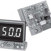
LED-Display, Subminiature DC Ammetersr
Datasheet
1.DCA5-20PC-1-DC4-RL-C.pdf
(6 pages)
Specifications of DCA5-20PC-7-DC1-RL-C
Equipment Type
LED-Display, Subminiature DC Ammeters
Input
50 mV
Lead Free Status / RoHS Status
Lead free / RoHS Compliant


TECHNICAL NOTES
1. Calibration: DCA5-20PC ammeters are designed to operate with
2. Wiring and Fusing: Power supply (TB2) and input (TB1) wiring must
3. Terminal Block Torque Ratings: It is important to tighten TB1’s and
4. High-Side versus Low-Side Shunts: Incorrect shunt connections
To ensure safe and reliable operation, DCA5-20PC dc ammeters
must only be installed and serviced by qualifi ed technical person-
nel. DC ammeter applications can expose a user to potentially
lethal currents and voltages. Power and signal connections must
be made with all associated power sources de-energized. Contact
DATEL if you have any questions regarding the installation or
operation of any of our digital instruments.
50mV and 100mV dc shunts whose rated accuracy is ±0.25%, or
better. The output of less accurate shunts may fall outside the amme-
ter’s ±1% calibration adjustment range. Under normal indoor operat-
ing conditions, periodic recalibration of DCA5-20PC ammeters is not
necessary. The calibration potentiometer, located on the back of the
ammeter, is a ¾ turn type; do not force its adjustment screw past the
two end stops.
If user calibration is deemed necessary, it must be performed by
qualifi ed personnel. Calibration is performed by applying a precision
50.00mVdc or 100mVdc (model specifi c, see ordering guide) signal to
TB1, observing correct polarity. Then, using an insulated slotted tool,
adjust the calibration potentiometer until the correct display reading is
achieved. Contact MPS if additional information is required regarding
calibration or setup of DCA5-20PC ammeters.
be rated for the electrical and environmental conditions under which
the ammeters will be operated. They must also comply with any regula-
tory or application-mandated requirements pertaining to the user’s
installation. Connections to DCA5-20PC ammeters must be made with
all power sources de-energized. Refer to the Functional Specifi cations
section for TB1 and TB2 wire gauge information.
DCA5-20PC ammeters’ shunt (TB1) and power supply inputs (TB2) are
not internally fused. Therefore, the supply wires connected to the meter
and the load should be fused according to the maximum current rating
(or lower) of the wire gauge used, in accordance with applicable regula-
tory codes. Insulation should be stripped to within +/-10% of the stated
dimensions. All wires must be inserted into the terminal block openings
such that the screw terminal does not pinch any insulation. TB2 is to
be used solely for powering the meter’s internal circuitry; it must not be
used to supply current to an external load or auxiliary device.
TB2’s screw-terminals to their rated torque specifi cations of 3.6 pound-
inches (0.4Nm). Proper tightening will minimize losses and ensure
reliable operation.
are one of the most common problems encountered when applying
digital dc-ammeters. Incorrect shunt connections can cause permanent
damage to the ammeter and/or its associated equipment.
Low-Side Shunts: Applications that employ a single power supply to power
both the load and the ammeter, and the external shunt is located in the
negative side of the supply (commonly referred to as “low side” or “grounded
shunt”) should use ‘-DC1’ non-isolated power DCA5-20PC Series ammeters.
Figures 2 and 3 depict typical low-side shunt connections.
www.murata-ps.com/dpm
BE IN LOW SIDE
SHUNT MUST
BE IN LOW SIDE
SHUNT MUST
Figure 3. Low-Side Shunt Connections for "-DC1" Models Modifi ed for
36-75Vdc Non-Isolated Power (See Technical Note 5)
Figure 2. Low-Side Shunt Connections for "-DC1"
–IN
50mV SHUNT
–IN
1
50mV SHUNT
1
5-40Vdc Non-Isolated Supply Models
TB1
TB1
+IN
50mV & 100mV Input, LED-Display,
DCA5-20PC-X-DC1-XX
DCA5-20PC-X-DC1-XX
2
+IN
CAL
2
CAL
03 May 2010 MPM_DCA5-20PC.B06 Page 3 of 6
DCA5-20PC Series
LOAD CURRENT
LOAD CURRENT
LOAD
Subminiature DC Ammeters
LOAD
1
2
J3
1
2
+V
J3
1
2
+V
J1 J2
1
1
2
J1 J2
1
TB2
email: sales@murata-ps.com
+
TB2
1
2
3
+
2
1
2
3
DC SUPPLY
1
–V
2
5-40Vdc
DC SUPPLY
1
–V
36-75Vdc
DEPEND ON INPUT RANGE
(FACTORY SETTING) FOR
J3 MUST BE INSTALLED
J1 AND J2 POSITIONS
FOR 36-75Vdc
5-40Vdc SUPPLIES
REMOVE J3
SUPPLIES
–
–
GROUND
POWER
(0Vdc)
GROUND
POWER
(0Vdc)
Related parts for DCA5-20PC-7-DC1-RL-C
Image
Part Number
Description
Manufacturer
Datasheet
Request
R

Part Number:
Description:
DC Ammeter 25/250A Ext. Shunt
Manufacturer:
Murata Power Solutions Inc
Datasheet:
Part Number:
Description:
DC Ammeter 25/250A Ext. Shunt
Manufacturer:
Murata Power Solutions Inc
Datasheet:
Part Number:
Description:
DC Ammeter 25/250A Ext. Shunt
Manufacturer:
Murata Power Solutions Inc
Datasheet:
Part Number:
Description:
DC Ammeter 25/250A Ext. Shunt
Manufacturer:
Murata Power Solutions Inc
Datasheet:
Part Number:
Description:
DC Ammeter 25/250A Ext. Shunt
Manufacturer:
Murata Power Solutions Inc
Datasheet:

Part Number:
Description:
Current Meter
Manufacturer:
Murata Power Solutions Inc
Datasheet:
Part Number:
Description:
Current Meter
Manufacturer:
Murata Power Solutions Inc
Datasheet:
Part Number:
Description:
Current Meter
Manufacturer:
Murata Power Solutions Inc
Datasheet:
Part Number:
Description:
DATEL PANEL METERS
Manufacturer:
Murata Power Solutions Inc
Datasheet:
Part Number:
Description:
DC Ammeter 5/50/500A Ext. Shunt
Manufacturer:
Murata Power Solutions Inc
Datasheet:

Part Number:
Description:
AMMETER LED 5-40VDC 1.999A RED
Manufacturer:
Murata Power Solutions Inc
Datasheet:

Part Number:
Description:
Transformers 5Vin 5Vout 200mA 4000Vdc 1:1.33 turn
Manufacturer:
Murata Power Solutions Inc
Datasheet:

Part Number:
Description:
POWER SUPPLY
Manufacturer:
Murata Power Solutions Inc
Datasheet:

Part Number:
Description:
DPM LED MINI 2VDC 3.5DIG LP RED
Manufacturer:
Murata Power Solutions Inc
Datasheet:

Part Number:
Description:
CONV DC/DC 1W 5VIN 5VOUT SIP SGL
Manufacturer:
Murata Power Solutions Inc
Datasheet: