DMS-40LCD-1/2-9-C Murata Power Solutions Inc, DMS-40LCD-1/2-9-C Datasheet - Page 2
DMS-40LCD-1/2-9-C
Manufacturer Part Number
DMS-40LCD-1/2-9-C
Description
DPM ±2/20V LCD 9V-Pwr
Manufacturer
Murata Power Solutions Inc
Datasheet
1.DMS-30-CP.pdf
(6 pages)
Specifications of DMS-40LCD-1/2-9-C
Display Type
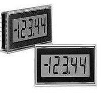
4 - 1/2 Digit LCD
Lead Free Status / RoHS Status
Lead free / RoHS Compliant


Performance/Functional Specifi cations
Typical at T
or +9V (using the differential input circuit), unless otherwise noted.
Analog Inputs
Full Scale Input Range: ➀
Input Impedence:
Overvoltage Protection ➁
Common Mode Voltage Range ➂
CMRR (dc to 60Hz)
Control Inputs ➃
Decimal Pt. Placement (Pins 4-6, 8):
Hold/Backlight Functionally (Pin 9)
Performance
Sampling Rate
Accuracy (1 minute warm-up):
Zero Reading (Vin = 0 Volts)
Temperature Drift (0 = +50°C)
Power Supply Requirements (5V Models)
Supply Voltage
Supply Current:
Power Supply Requirements (9V Models)
Supply Voltage
Supply Current:
Display
Display Type and Size
Polarity Indication
Overrange Indication
DMS-40LCD-0/1
DMS-40LCD-1/2
DMS-40LCD-2/3
DMS-40LCD-0/1
DMS-40LCD-1/2
DMS-40LCD-2/3
Functionality
Logic Compatibility
Backlit Models
Non-backlit Models
DMS-40LCD-0/1 (Vin = +0.19/1.9V)
DMS-40LCD-1/2 (Vin = +1.9V)
DMS-40LCD-1/2 (Vin = +19V)
DMS-40LCD-2/3 (Vin = +19/190V)
DMS-40LCD-0/1
DMS-40LCD-1/2
DMS-40LCD-2/3
Standard Models
Backlit Models
Standard Models
Backlit Models
A
= +25°C and supply voltage = +5V (using the single-ended input circuit)
“–001”
Min.
+4.75
+7.5
100
0.8
0.8
–
–
–
–
–
–
–
–
–
–
–
–
–
–
–
–
–
Autopolarity ("–" for negative Vin)
4½ digit, 0.4"/10.2mm high LCD
"–1_ _ _ _ " for negative inputs
TTL (on 5V-powered models)
"1_ _ _ _ " for positive inputs
Tie to pin 3 to hold reading
2.5 reading per second
Tie to pin 3 to activate
Tie to pin 1 to activate
±20/±200
±200/±2
+5.00
+2.5
+37
+9.00
+1.5
+37
±2/±20
Typ.
1000
“000”
±0.4
±0.6
±0.6
86
±2
±2
±3
±3
1
1
–
–
+5.25
+3.5
+45
+14.0
+2.5
+45
Max.
“001”
±250
±0.8
±2
±3
±3
±4
±4
±1
±1
–
–
–
–
–
–
www.murata-ps.com/dpm
Volts
Volts
Cnts/°C
Cnts/°C
Cnts/°C
Counts
Counts
Counts
Counts
Units
mV/V
Volts
Volts
MΩ
MΩ
MΩ
mA
mA
mA
mA
V/V
V/V
dB
➀ Each model in the DMS-40LCD Series offers two input voltage ranges that are
user-selectable via pin strapping. 5V-powered models can be used to perform either
differential or single-ended measurements. 9V-powered models can only be used for
differential measurements.
➁ Applies for transient or continuous overvoltages applied to (+) INPUT HI (pin 11)
with (–) INPUT LO (pin 12) properly connected. Pin 12 is not overvoltage protected
(see Figure 1). Voltages applied to pin 12 should not exceed the supply voltage.
➂ Listed spec applies to 5V-powered models only. For 9V-powered models, both
(–) INPUT LO (pin 12) and (+) INPUT HIGH (pin 11) must always be at least 1.5V
above –BATTERY (pin 3) and at least 1.5V below +BATTERY (pin 1).
➃ See Technical Notes.
1. Input Voltage Range Selection: Each model in the DMS-40LCD
2. Decimal Point Placement: The location of the decimal point is user-
TECHNICAL NOTES
Physical/Environmental
Operating Temperature
Storage Temperature
Humidity (non-condensing)
Case Material
Weight
Ordering Information
Input Ranges:
DMS-40LCD - 0/1 - 5
Series offers two, user-selectable, input voltage ranges as indicated
in the Performance/Functional Specifi cations Table and the Ordering
Information. To select the higher range of any device (such as the ±2V
range for the DMS-40LCD-0/1), connect pin 2 (RANGE SELECT) to
pin 1 (+5V SUPPLY/+BATTERY). To select the lower range, leave pin 2
open.
selectable, and the decimal point control pins (DP1-DP4) are active low
functions. Select the appropriate decimal point by tying the appropriate
pin (pin 4, 5, 6 or 8) to pin 3 (5V RETURN/–BATTERY). Unused deci-
mal point location pins should be left open. For 5V-powered models,
the decimal location pins are TTL compatible and may be hard wired as
described above or driven with 5V TTL logic gates.
Accessories:
0/1 = ±200mV/±2V
1/2 = ±2V/±20V
2/3 = ±20V/±200V
DMS-30-CP
DMS-BZL1-C
DMS-BZL2-C
DMS-EB-C
4½ Digit, LCD Display Digital Panel Voltmeters
A panel-mount retaining clip is supplied with each model.
Panel cutout punch
DMS-40 bezel assembly
DMS-40 bezel assembly with sealing gasket
Application/evaluation board with standard
MOLEX connector, decimal point solder pads
and attenuation resistor pads.
DMS-40LCD Series
Power Source:
5 = +5V
9 = +9V
04/05/11 MPM_DMS40LCD.C04 Page 2 of 6
–20
0
0
-C
email: sales@murata-ps.com
0.75 ounces (21 grams)
Polycarbonate
–
–
–
Leave blank for standard
models. Add B for
backlit models.
Add -C for RoHS
+50
+75
95
°C
°C
%
Related parts for DMS-40LCD-1/2-9-C
Image
Part Number
Description
Manufacturer
Datasheet
Request
R

Part Number:
Description:
DPM ±.2/2V LCD BakLite 9V-Pwr
Manufacturer:
Murata Power Solutions Inc
Datasheet:
Part Number:
Description:
DPM ±2/20V LCD BakLite 5V-Pwr
Manufacturer:
Murata Power Solutions Inc
Datasheet:
Part Number:
Description:
DPM ±20/200V LCD BkLite 5V-Pwr
Manufacturer:
Murata Power Solutions Inc
Datasheet:
Part Number:
Description:
DPM ±20/200V LCD BkLite 9V-Pwr
Manufacturer:
Murata Power Solutions Inc
Datasheet:

Part Number:
Description:
Voltage Meter
Manufacturer:
Murata Power Solutions Inc
Datasheet:

Part Number:
Description:
POWER OVER ETHERNET MODULE
Manufacturer:
Murata Power Solutions Inc
Datasheet:

Part Number:
Description:
POWER OVER ETHERNET MODULE
Manufacturer:
Murata Power Solutions Inc
Datasheet:

Part Number:
Description:
POWER OVER ETHERNET MODULE
Manufacturer:
Murata Power Solutions Inc
Datasheet:

Part Number:
Description:
POWER OVER ETHERNET MODULE
Manufacturer:
Murata Power Solutions Inc
Datasheet:

Part Number:
Description:
Power Inductors 2.2mH1.4A
Manufacturer:
Murata Power Solutions Inc
Datasheet:

Part Number:
Description:
Digital Panel Meters DMS-20 BezelAssembly Panel mount
Manufacturer:
Murata Power Solutions Inc
Datasheet:

Part Number:
Description:
DPM LED MINI 2VDC 3.5DIG LP RED
Manufacturer:
Murata Power Solutions Inc
Datasheet:

Part Number:
Description:
DPM LED 2VDC 4.5DIGIT GREEN
Manufacturer:
Murata Power Solutions Inc
Datasheet:

Part Number:
Description:
DPM LED 2VDC 3.5DIGIT LP RED
Manufacturer:
Murata Power Solutions Inc
Datasheet:

Part Number:
Description:
Transformers 5Vin 5Vout 200mA 4000Vdc 1:1.33 turn
Manufacturer:
Murata Power Solutions Inc
Datasheet: