IEGH66-1-72-30.0-01-V AIRPAX, IEGH66-1-72-30.0-01-V Datasheet - Page 13
IEGH66-1-72-30.0-01-V
Manufacturer Part Number
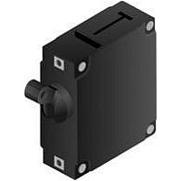
IEGH66-1-72-30.0-01-V
Description
CIRCUIT BREAKER, HYD-MAG, 2P, 240V, 30A
Manufacturer
AIRPAX
Series
IEGr
Datasheet
1.IEG6-1-72-10.0-01-V.pdf
(24 pages)
Specifications of IEGH66-1-72-30.0-01-V
Input Voltage Vac
240V
No. Of Poles
2
Current Rating
30A
Interrupting Capacity
7.5kA
Dielectric Strength
3.75kV
Trip Time
20s
Voltage Rating Vdc
80V
Lead Free Status / RoHS Status
Lead free / RoHS Compliant


http://airpax.sensata.com/
DCR and Impedance based on 100% rated current applied and stabalized for
a minimum of one hour. Tolerance .05-2.5 amperes ± 20%: 2.6 -20 amperes
± 25%, 21-50 amperes ± 50%. Consult factory for special values and for coil
impedance of delays not shown.
*CEG type units are available only with 51, 52, ,53 and 59 delays LEG type units are available only with 61, 62, 63 and 69 delays
**135% minimum trip point for delays 71, 72, 73 and 79
Current Ratings
TYPICAL RESISTANCE / IMPEDANCE
PERCENTAGE OF RATED CURRENT VS TRIP TIME IN SECONDS AT +25°C (VERTICAL MOUNT)
Delay
71**
72**
73**
79**
51*
52*
53*
59*
61*
62*
63*
69*
(Amps)
41
42
43
49
64
65
66
0.200
1.00
2.00
5.00
10.0
20.0
30.0
50.0
No Trip
No Trip
No Trip
No Trip
No Trip
No Trip
No Trip
No Trip
No Trip
No Trip
No Trip
No Trip
No Trip
No Trip
No Trip
No Trip
No Trip
No Trip
No Trip
100%
51, 52, 53, 59
(ohms)
0.0027
0.0019
0.053
0.016
0.006
36.6
1.38
0.31
DC
.700 to 12
.440 to 10
1.8 to 100
May Trip
May Trip
May Trip
May Trip
.120 Max
.120 Max
.120 Max
.500 to 6.5
80 to 700
10 to 120
50 to 700
10 to 120
50 to 700
50 to 600
.7 to 12
2 to 60
125%
61, 62, 63, 69
AC, 50/60Hz
Impedance
(ohms)
0.0026
0.0018
0.051
0.013
0.005
34.2
1.47
0.25
.100 Max
.050 Max
.100 Max
.100 Max
.500 to 8.0
35 to 350
.300 to 3.0
40 to 400
.35 to 7.0
30 to 400
30 to 400
30 to 400
1.8 to 30
.300 to 7
1.7 to 60
.35 to 7
5 to 70
6 to 60
6 to 60
150%
41, 42, 43, 49
AC, 400Hz
(ohms)
0.004
0.100
0.027
0.008
74.2
2.85
0.64
—
IAG/IUG/IEG/CEG/LEG Series - Operating Characteristics
.130 to 3.0
.100 to 3.0
.050 Max
.050 Max
.050 Max
.150 to 1.9
12 to 120
.100 to 1.2
15 to 150
10 to 150
10 to 150
10 to 150
.050 Max
2.2 to 25
.13 to 3
1 to 10
2 to 20
2 to 20
1 to 20
200%
INRUSH PULSE TOLERANCE
OPERATING CHARACTERISTICS
Inrush Pulse Tolerance
The following table provides a comparison of inrush
pulse tolerance with and without the inertial delay
feature for each of the 50/60Hz delays. Pulse
tolerance is defined as a single pulse of half sine
wave peak current amplitude of 8 milliseconds
duration that will not trip the circuit breaker. The
table at left provides a guide to determine if the
inertia delay feature is required. Consult factory for
further assistance.
.031 to .500
61F, 62F, 63F, 71F, 72F, 73F
.020 Max
.022 Max
.022 Max
.020 to .40
.40 to 5.0
.15 to 2.0
.023 Max
1.5 to 20
.030 to 1
1.5 to 20
.030 to 1
1.5 to 20
1.8 to 20
.2 to 3.0
.03 to 1
.15 to 3
2 to 20
.2 to 3
61, 62, 63, 71, 72, 73
400%
64, 65, 66
Delay
.012 to 2.2
.020 Max
.017 Max
.006 to .25
.011 to .25
.015 to .3
.017 to .3
.017 Max
.012 to .3
.016 Max
.012 to 2
.22 to 10
.04 to 1
.23 to 9
.02 to 2
.4 to 10
.02 to 2
.4 to 10
.04 to 2
600%
10 times rated current (approx)
12 times rated current (approx)
25 times rated current (approx)
.018 to .55
.013 to .85
.017 to .76
.004 to .15
.008 to .79
.018 to .88
.020 Max
.017 Max
.006 to .2
.01 to .22
.008 to .5
.01 to .15
.015 to .8
.01 to .16
.017 Max
.015 Max
.014 to 5
.004 to .1
.004 to .1
800%
Pulse Tolerance
.006 to .15
.006 to .28
.011 to .50
.020 Max
.017 Max
.004 to .05
.004 to .08
.006 to .1
.012 to .2
.008 to .1
.01 to .25
.013 to .5
.017 Max
.015 Max
.008 to .1
.004 to .1
.014 to 3
.01 to .1
.01 to. 6
1000%
116
Related parts for IEGH66-1-72-30.0-01-V
Image
Part Number
Description
Manufacturer
Datasheet
Request
R

Part Number:
Description:
CIRCUIT BREAKER HYMAG DP 40A
Manufacturer:
Sensata Technologies/Airpax
Datasheet:

Part Number:
Description:
CIRCUIT BREAKER HYMAG DP 50A
Manufacturer:
Sensata Technologies/Airpax
Datasheet:

Part Number:
Description:
CIRCUIT BREAKER, HYD-MAG, 2P, 240V, 10A
Manufacturer:
AIRPAX
Datasheet:
Part Number:
Description:
CIRCUIT BREAKER, HYD-MAG, 2P, 240V, 15A
Manufacturer:
AIRPAX
Datasheet:
Part Number:
Description:
CIRCUIT BREAKER, HYD-MAG, 2P, 240V, 20A
Manufacturer:
AIRPAX
Datasheet:
Part Number:
Description:
CIRCUIT BREAKER, HYD-MAG, 2P, 240V, 50A
Manufacturer:
AIRPAX
Datasheet:
Part Number:
Description:
CIRCUIT BREAKER, HYD-MAG, 2P, 240V, 5A
Manufacturer:
AIRPAX
Datasheet:

Part Number:
Description:
CIRCUIT BREAKER, HYD-MAG, 2P, 250V, 30A
Manufacturer:
AIRPAX
Datasheet:

Part Number:
Description:
CIRCUIT BREAKER HYMAG DP 20A
Manufacturer:
Sensata Technologies/Airpax
Datasheet:
