1110-F112-P1M1-1A ETA, 1110-F112-P1M1-1A Datasheet
1110-F112-P1M1-1A
Manufacturer Part Number
1110-F112-P1M1-1A
Description
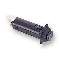
CIRCUIT BREAKER, 1A
Manufacturer
ETA
Series
1110r
Datasheet
1.1110-F112-P1M1-0.5A.pdf
(2 pages)
Specifications of 1110-F112-P1M1-1A
Voltage Rating Vdc
28V
Voltage Rating Vac
250V
Fuse Current
1A
No. Of Poles
1
Mounting Type
Panel Mount
Approval Bodies
BUREAU VERITAS, CSA, EN60934, LLOYDS, SEMKO, UL, VDE
Breaking Capacity
RoHS Compliant
Current Rating
1A
Svhc
No SVHC (15-Dec-2010)
Rohs Compliant
Yes


Single pole switch/thermal circuit breaker (S-type TO CBE to EN 60934)
with tease-free, trip-free, snap action mechanism. Designed for snap-
in panel mounting utilising round hole or industry standard fuse-
holder cut-out dimensions. Featuring an ergonomically styled two
colour actuator with indicator band clearly showing the tripped/OFF
position.
Approved to CBE standard EN 60934 (IEC 60934).
Motors, transformers, solenoids, extra low voltage systems,
household and office machines, instrumentation, marine
applications, mobile homes.
Type No.
1110
1110 - F1 1 2 - P1 M1 - 0.05 A
Current
rating (A)
0.05
0.08
0.1
0.2
0.3
0.4
0.5
0.6
0.7
0.8
1
1.2
1.5
1.8
Authority
BV
UL
CSA
VDE
05/06
Description
Typical applications
Ordering information
Standard current ratings and typical internal resistance values
Approvals
(280405)
snap in panel mounting
Mounting
F1
F2
panel thickness 0.8...1.6 mm (.031 -.063 in)
panel thickness 1.8...3 mm (.071-.118 in)
Number of poles
1
1 pole protected
Actuator style
2
Internal
resistance (
442
173
110
27.8
12.4
7.0
4.5
3.1
2.3
1.7
1.1
0.71
0.41
0.38
black push button/white indicator ring, standard
Other indicator ring colours are available to special order
Terminal design
P1
Thermal Overcurrent Circuit Breaker 1110-...
blade terminals A6.3-0.8 (QC .250)
Characteristic curve
M1
Voltage ratings
AC 250 V; DC 28 V
AC 250 V
AC 125 V
DC 50 V
AC 250 V; DC 50 V
AC 250 V
medium delay
Current ratings
0.05...16A
Ω
)
= ordering example
Current
rating (A)
2
2.5
3
3.5
4
5
6
7
8
10
12
15
16
Current ratings
0.05...16 A
0.05...6 A
7...16 A
0.05...16 A
0.05...16 A
0.05...10 A
Internal
resistance (
0.25
0.19
0.12
0.09
0.07
0.05
0.04
≤ 0.02
≤ 0.02
≤ 0.02
≤ 0.02
≤ 0.02
≤ 0.02
www.e-t-a.com
Ω
)
For further details please see chapter: Technical Information
Voltage rating
Current rating
Typical life
Ambient temperature
Insulation co-ordination
(IEC 60664 and 60664 A)
Dielectric strength
(IEC 60664 and 60664A)
Insulation resistance
Interrupting capacity I
Interrupting capacity
(UL 1077/EN60934 PC 1)
Degree of protection
(IEC 60529/DIN 40050)
Vibration
Shock
Corrosion
Humidity
Mass
Technical data
operating area
AC + DC
0.05...10 A 10,000 operations at 1 x I
12...16 A
cn
AC 250 V; DC 28 V
(UL: AC 250 V; DC 50 V)
0.05...16 A
6,000 operations at 1 x I
-20...+60 °C (-4...+140 °F)
rated impulse
withstand voltage
2.5 kV
reinforced insulation in operating area
test voltage
AC 3,000 V
> 100 M
AC 250 V:
DC 28 V:
I
0.05...6 A
7...16 A
0.05...16 A
operating area IP40
terminal area IP00
8 g (57-500 Hz)±0.61 mm (10-57 Hz),
to IEC 60068-2-6, test Fc,
10 frequency cycles/axis
30 g (11 ms)
to IEC 60068-2-27, test Ea
96 hours at 5 % salt mist,
to IEC 60068-2-11, test Ka
240 hours at 95 % RH
to IEC 60068-2-3, test Ca
approx. 12 g
1110-F1..
N
Ω
(DC 500 V)
0.05...16 A
0.05...6 A
7...10 A
12...16 A
U
AC 250 V
AC 125 V
DC 50 V
N
pollution
degree
2
N
N
, inductive
, inductive
8 x I
10 x I
200 A
300 A
1,000 A
1,000 A
1,000 A
N
N
1
Related parts for 1110-F112-P1M1-1A
Image
Part Number
Description
Manufacturer
Datasheet
Request
R

Part Number:
Description:
CIRCUIT BREAKER, 0.5A
Manufacturer:
ETA
Datasheet:
Part Number:
Description:
CIRCUIT BREAKER, 10A
Manufacturer:
ETA
Datasheet:
Part Number:
Description:
CIRCUIT BREAKER, 16A
Manufacturer:
ETA
Datasheet:
Part Number:
Description:
CIRCUIT BREAKER, 2A
Manufacturer:
ETA
Datasheet:
Part Number:
Description:
CIRCUIT BREAKER, 3A
Manufacturer:
ETA
Datasheet:
Part Number:
Description:
CIRCUIT BREAKER, 5A
Manufacturer:
ETA
Datasheet:


Part Number:
Description:
PHONE HI-D JACK .25" 2COND SLD
Manufacturer:
Switchcraft Inc.
Datasheet:

Part Number:
Description:
TOOLS,CRIMP,HAND,CRIMPING TOOL, HEAVY-DUTY, LEVER-TYPE, 8 AWG, 6 AWG, 4 AWG, 2 AWG,TERMINALS & SPLICES,HEAVY-DUTY LEVER-TYPE CRIMPING TOOLS ,HOFFMAN PRODUCTS
Manufacturer:
HOFFMAN PRODUCTS
Datasheet:


Part Number:
Description:
No.111 , Stair Gage Fixture Attachments, For Rafter And Framing Squares (Pair) - Long
Manufacturer:
STARRETT
1110-F112-P1M1-1A Summary of contents
Page 1
... Other indicator ring colours are available to special order Terminal design P1 blade terminals A6.3-0.8 (QC .250) Characteristic curve M1 medium delay Current ratings 0.05...16A 1110 - 0. ordering example Standard current ratings and typical internal resistance values Current Internal Current rating (A) resistance ( ) rating (A) Ω ...
Page 2
... Thermal Overcurrent Circuit Breaker 1110-... Dimensions 1110-F1.. / -F2.. When installing the circuit breaker apply pressure on bezel only. 19 .748 10 1 .394 12.1 .476 15.6 .61 blade terminals DIN 46244-A6.3-0.8 (QC .250) Panel cut out 1110-F1..-P.M1-...A +0.2 ±0.05 - 0.4 ±.002 +.008 - .016 installation side 0.8 … ...