HFD3100 EATON CUTLER HAMMER, HFD3100 Datasheet - Page 3
HFD3100
Manufacturer Part Number
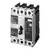
HFD3100
Description
CIRCUIT BREAKER, THERMAL MAG, 3P, 100A
Manufacturer
EATON CUTLER HAMMER
Series
HFDr
Datasheet
1.EHMVD06B.pdf
(276 pages)
Specifications of HFD3100
Actuator Style
Toggle
No. Of Poles
3
Current Rating
100A
Voltage Rating Vdc
250V
Voltage Rating Vac
600V
Mounting Type
DIN Rail
Terminals
Screw


November 2008
General Information
Cutler-Hammer Series G Molded Case
Circuit Breakers provide increased
performance in considerably less
space than standard circuit breakers
or comparable fusible devices.
The “G” signifies global applications:
Series G circuit breakers are marked
with UL, CSA , CE, IEC and KEMA
KEUR listings. Other advantages
include:
■
■
■
■
■
The EG, JG and LG frames are
designed around space-saving foot-
prints. The NG and RG use the proven
Cutler-Hammer Series C ND and RD
designs but use metric threading on
their line and load conductors.
Cutler-Hammer Series G Circuit
Breakers meet applicable UL 489
and IEC 60947-2 standards.
The Cutler-Hammer Series G family
includes five frame sizes in ratings
from 15 to 2500 amperes. Series G
offers a choice of several interrupting
capacities up to 200 kA at 480 volts ac
(200 kA at 240 volts ac).
Standard calibration is 40°C. For appli-
cations in high ambient temperature
conditions, 50°C factory calibration
is available on thermal magnetic
breakers (not UL).
CA08101001E
Field-fit accessories.
Common accessories through
630 amperes.
Electronic trip units from 20 to
2500 amperes.
UL-listed and IEC-rated, 30 mA
ground fault/earth leakage modules.
Built-in ground fault protection
down to 20 amperes.
The Most Logically Designed
Contact Assembly
The flexibility and outstanding
performance characteristics of Cutler-
Hammer Circuit Breakers are made
possible by the best contact designs
in circuit breaker history. Our patented
technology creates a high-speed
“blow-open” action using the
electromechanical forces produced
by high-level fault currents.
Cutler-Hammer Circuit Breakers are
operated by a toggle-type mechanism
that is mechanically trip-free from
the handle so that the contacts cannot
be held closed against short circuit
currents. Tripping due to overload or
short circuits is clearly indicated by the
position on the handle. This remark-
ably fast and dependable contact
action is designed to enhance safety.
Thorough In-Plant Testing
The quality, dependability and reliability
of every Cutler-Hammer Circuit Breaker
is ensured by a thorough program
of in-plant testing. Two calibration
tests are conducted on every pole of
every circuit breaker to verify the trip
mechanism, operating mechanism,
continuity and accuracy.
ISO Certification
Cutler-Hammer Circuit Breakers
are manufactured in ISO certified
facilities.
For more information visit: www.eaton.com
Series G Molded Case Circuit Breakers
15 – 2500 Amperes for UL, CSA & IEC Applications
Product Line Overview
Current Limiting Characteristics
Circuit breakers are current limiting
because of their high repulsion contact
arrangement and use of state-of-
the-art arc extinguishing technology.
Eaton offers one of the most
complete lines of current limiting
breakers in the industry. The industrial
breakers are available in current
limiting versions with interrupting
capacities up to 200 kA at 480 V
without fuses in the same physical size
as standard and high interrupting
capacity breakers.
Operating Mechanisms
Cutler-Hammer Circuit Breakers have
a toggle handle operating mechanism,
which also serves as a switching
position indicator. The indicator shows
the positions of: ON, OFF and TRIPPED.
The toggle handle snaps into the
TRIPPED position if the breaker is
tripped by one of its overcurrent, short
circuit, shunt or undervoltage releases.
Before the circuit breaker can be
reclosed following a trip-out, the tog-
gle handle must be brought beyond
the OFF position (RESET). The circuit
breaker can then be reclosed.
As an additional switching position
indicator for EG- to RG-Frame circuit
breakers, there are two windows on
the right and on the left of the toggle
handle, in which the switching state
is indicated by means of the colors
red, green and white corresponding to
the ON, OFF and TRIPPED positions
respectively.
Figure 12-2. Positions of the Toggle
Handle Drive
OFF
RESET
ON
Tripped
12-3
12
Related parts for HFD3100
Image
Part Number
Description
Manufacturer
Datasheet
Request
R

Part Number:
Description:
PROGRAMMABLE LOGIC CONTROLLER
Manufacturer:
EATON CUTLER HAMMER
Part Number:
Description:
Pm Power Pro 3000/5000 A-B Accel/On Interface
Manufacturer:
EATON CUTLER HAMMER
Part Number:
Description:
Handle Tie Bar For (2) - 1 Pole Type BR Breakers
Manufacturer:
EATON CUTLER HAMMER
Part Number:
Description:
Type CH Breaker 150A/2 Pole 120/240V 10K
Manufacturer:
EATON CUTLER HAMMER
Part Number:
Description:
Tenant Branch Breaker 125A/3 Pole 120/240V 42K
Manufacturer:
EATON CUTLER HAMMER
Part Number:
Description:
Type CL Breaker 25A/1Pole 120/240V 10K-Classified 1" Ckt Bkr
Manufacturer:
EATON CUTLER HAMMER
Part Number:
Description:
FD BREAKER 1P 80 AMP WITH LOAD ONLY TERMINALS
Manufacturer:
EATON CUTLER HAMMER
Part Number:
Description:
GD 2 POLE BREAKER, 25 AMP, SINGLE PACKED
Manufacturer:
EATON CUTLER HAMMER
Part Number:
Description:
Handle Tie Bar For (2) - 1 Pole Type BR Breakers
Manufacturer:
EATON CUTLER HAMMER
Part Number:
Description:
Type CL Breaker 25A/1Pole 120/240V 10K-Classified 1" Ckt Bkr
Manufacturer:
EATON CUTLER HAMMER