B72214S0200K101 EPCOS Inc, B72214S0200K101 Datasheet - Page 18
B72214S0200K101
Manufacturer Part Number
B72214S0200K101
Description
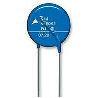
VARISTOR, 6.0J, 20VAC
Manufacturer
EPCOS Inc
Series
B722r
Datasheet
1.S05K140.pdf
(36 pages)
Specifications of B72214S0200K101
Suppressor Type
Varistor
Clamping Voltage Vc Max
65V
Peak Energy (10/1000us)
6J
Voltage Rating Vdc
26V
Voltage Rating Vac
20V
Operating Temperature Range
-40°C To +85°C
Svhc
No SVHC
Product
MOV
Voltage Rating Dc
26 V
Voltage Rating Ac
20 V
Clamping Voltage
65 V
Peak Surge Current
1 KA
Capacitance
6800 pF
Mounting
Radial
Tolerance
10 %
Lead Free Status / RoHS Status
Lead free / RoHS Compliant


Reliability data
Test
Varistor voltage
Clamping voltage
Max. AC operating voltage
Surge current derating,
8/20 µs
Surge current derating,
2 ms
Electric strength
Please read Cautions and warnings and
Important notes at the end of this document.
Leaded varistors
StandarD series
Test methods/conditions
The voltage between two terminals with
the specified measuring current applied
is called V
The maximum voltage between two
terminals with the specified standard
impulse current (8/20 µs) applied.
CECC 42 000, test 4.20
1000 h at UCT
After having continuously applied
the maximum allowable voltage at UCT
±2 °C for 1000 h, the specimen shall be
stored at room temperature and normal
humidity for 1 to 2 h.
Thereafter, the change of V
measured.
CECC 42 000, test C 2.1
100 surge currents (8/20 µs), unipolar,
interval 30 s, amplitude corresponding
to derating curve for 100 impulses at
20 µs
CECC 42 000, test C 2.1
100 surge currents (2 ms), unipolar,
interval 120 s, amplitude corresponding
to derating curve for 100 impulses at
2 ms
CECC 42 000, test 4.7
Metal balls method, 2500 V
The varistor is placed in a container
holding 1.6 ±0.2 mm diameter metal
balls such that only the terminations of
the varistor are protruding.
The specified voltage shall be applied
between both terminals of the speci-
men connected together and the elec-
trode inserted between the metal balls.
v
(1 mA
DC
18
@ 0.2 … 2 s).
11/07
RMS
v
shall be
, 60 s
Requirement
To meet the specified value.
To meet the specified value.
|
|
(measured in direction
of surge current)
No visible damage
|
(measured in direction
of surge current)
No visible damage
No breakdown
∆V/V (1 mA)
∆V/V (1 mA)
∆V/V (1 mA)
|
|
|
≤10%
≤10%
≤10%
Related parts for B72214S0200K101
Image
Part Number
Description
Manufacturer
Datasheet
Request
R


Part Number:
Description:
B72214-S151-K101 VARISTOR 14MM 150VAC
Manufacturer:
TDK Corporation
Part Number:
Description:
B72214-S381-K101V57 VARISTOR
Manufacturer:
TDK Corporation


