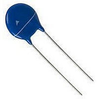
B72210S200K101 EPCOS Inc, B72210S200K101 Datasheet - Page 20

B72210S200K101
Manufacturer Part Number
B72210S200K101
Description
METAL OXIDE VARISTOR, 26V, 65V, RAD
Manufacturer
EPCOS Inc
Type
MOVr
Datasheet
1.S05K140.pdf
(36 pages)
Specifications of B72210S200K101
Suppressor Type
Varistor
Peak Surge Current @ 8/20µs
500A
Varistor Case
10mm DISC
Clamping Voltage Vc Max
65V
Peak Energy (10/1000us)
3.1J
Voltage Rating Vdc
26V
Voltage Rating Vac
20V
Brand/series
Standard Series
Capacitance
3650 pF
Current, Peak
500 A
Dimensions
12.0 mm (Max.) Dia. x 4.5 mm (Max.) W x 14.5 mm (Max.) H
Electric Strength
2.5 kV (RMS) (Min.)
Energy Rating
3.1 Joules
Mounting Style
Leaded
Package
Leads
Power Rating
0.05 W (Max.) @ +85 °C
Resistance, Insulation
10 Megohms (Min.)
Technology
Metal Oxide
Temperature, Operating, Maximum
85 °C
Temperature, Operating, Minimum
-40 °C
Terminal Type
Tinned Copper
Time, Response
25 ns (Max.)
Voltage, Ac
20 VAC
Voltage, Clamping
65 V
Voltage, Dc
26 VDC
Voltage, Operating
20 Vrms @ +85 °C, 26 VDC @ +85 °C
Voltage, Varistor
33
Lead Free Status / RoHS Status
Lead free / RoHS Compliant
Reliability data
Test
Resistance to soldering heat IEC 60068-2-20, test Tb, method 1A,
Tensile strength
Vibration
Bump
Flammability
Note:
UCT = Upper category temperature / LCT = Lower category temperature / R
Please read Cautions and warnings and
Important notes at the end of this document.
Leaded varistors
StandarD series
Test methods/conditions
260 °C, 10 s:
Each lead shall be dipped into a solder
bath having a temperature of 260 ±5 °C
to a point 2.0 to 2.5 mm from the body of
the specimen, be held there for 10 ±1 s
and then be stored at room temperature
and normal humidity for 1 to 2 h.
The change of V
and the specimen shall be visually
examined.
IEC 60068-2-21, test Ua1
After gradually applying the force
specified below and keeping the unit
fixed for 10 s, the terminal shall be
visually examined for any damage.
Force for wire diameter:
0.6 mm = 10 N
0.8 mm = 10 N
1.0 mm = 20 N
IEC 60068-2, test Fc
Frequency range: 10 … 55 Hz
Amplitude:
Duration:
Pulse:
After repeatedly applying a single
harmonic vibration according to the
table above.
The change of V
and the specimen shall be visually
examined.
IEC 60068-2-29, test Eb
Pulse duration:
Max. acceleration: 400 m/s
Number of bumps: 4000
Pulse:
IEC 60695-2-2 (needle flame test)
Severity: vertical 10 s
v
v
shall be measured
shall be measured
20
0.75 mm or 98 m/s
6 h (3 · 2 h)
sine wave
half sine
6 ms
11/07
2
ins
= Insulation resistance to CECC 42 000, test 4.8
2
Requirement
|
No visible damage
|
No break of solder joint,
no wire break
|
No visible damage
|
No visible damage
5 s max.
∆V/V (1 mA)
∆V/V (1 mA)
∆V/V (1 mA)
∆V/V (1 mA)
|
|
|
|
≤5%
≤5%
≤5%
≤5%


