SM15T220A-E3/57T Vishay, SM15T220A-E3/57T Datasheet

TRANSIENT SUPPRESSOR DIODE,SINGLE,UNIDIRECTIONAL,188V V(RWM),DO-214AB

SM15T220A-E3/57T

Manufacturer Part Number
SM15T220A-E3/57T
Description
TRANSIENT SUPPRESSOR DIODE,SINGLE,UNIDIRECTIONAL,188V V(RWM),DO-214AB
Manufacturer
Vishay
Series
TransZorb® SM15Tr

Specifications of SM15T220A-E3/57T

Voltage - Reverse Standoff (typ)
188V
Voltage - Breakdown
209V
Power (watts)
1500W
Polarization
Unidirectional
Mounting Type
Surface Mount
Package / Case
DO-214AB, SMC
Polarity
Unidirectional
Channels
1 Channel
Clamping Voltage
388 V
Operating Voltage
188 V
Breakdown Voltage
209 V
Peak Surge Current
200 A
Peak Pulse Power Dissipation
1500 W
Maximum Operating Temperature
+ 150 C
Minimum Operating Temperature
- 65 C
Dimensions
6.22(Max) mm W x 7.11(Max) mm L
Lead Free Status / RoHS Status
Lead free / RoHS Compliant
Other names
SM15T220A-E3/9AT
MECHANICAL DATA
Case: DO-214AB (SMC)
Molding compound meets UL 94 V-0 flammability
rating
Base P/N-E3 - RoHS compliant, commercial grade
Base P/NHE3 - RoHS compliant, high reliability/
automotive grade (AEC Q101 qualified)
Terminals: Matte tin plated leads, solderable per
J-STD-002 and JESD22-B102
E3 suffix meets JESD 201 class 1A whisker test, HE3
suffix meets JESD 201 class 2 whisker test
Polarity: For uni-directional types the band denotes
cathode end, no marking on bi-directional types
DEVICES FOR BI-DIRECTION APPLICATIONS
For bi-directional devices use CA suffix (e.g.
SM15T12CA).
Electrical characteristics apply in both directions.
Notes:
(1) Non-repetitive current pulse, per Fig. 3 and derated above T
(2) Mounted on 0.31 x 0.31" (8.0 x 8.0 mm) copper pads to each terminal
Document Number: 88380
Revision: 21-Oct-08
PRIMARY CHARACTERISTICS
MAXIMUM RATINGS (T
PARAMETER
Peak pulse power dissipation with a 10/1000 µs waveform
Peak power pulse current with a 10/1000 µs waveform
Power dissipation on infinite heatsink T
Peak forward surge current 10 ms single half sine-wave uni-directional only
Operating junction and storage temperature range
I
FSM
Surface Mount T
(uni-directional only)
T
P
J
V
P
PPM
max.
BR
D
DO-214AB (SMC)
PDD-Americas@vishay.com, PDD-Asia@vishay.com, PDD-Europe@vishay.com
For technical questions within your region, please contact one of the following:
A
= 25 °C unless otherwise noted)
A
RANS
= 50 °C
6.8 V to 220 V
1500 W
150 °C
6.5 W
200 A
Z
ORB
(1)
(Fig. 3)
(1)(2)
A
(Fig. 1)
= 25 °C per Fig. 2
®
Transient Voltage Suppressors
FEATURES
APPLICATION NOTES
A 1500 W (SMC) device is normally selected when the
threat of transients is from lightning induced transients,
conducted via external leads or I/O lines. It is also used
to protect against switching transients induced by
large coils or industrial motors. Source impedance at
component level in a system is usually high enough to
limit the current within the peak pulse current (I
rating of this series. In an overstress condition, the
failure mode is a short circuit.
TYPICAL APPLICATIONS
Use in sensitive electronics protection against voltage
transients induced by inductive load switching and
lighting on ICs, MOSFET, signal lines of sensor units
for consumer, computer, industrial, automotive and
telecommunication.
• Low profile package
• Ideal for automated placement
• Glass passivated chip junction
• 1500 W peak pulse power capability with a
• Available in uni-directional and bi-directional
• Excellent clamping capability
• Low inductance
• Meets MSL level 1, per J-STD-020, LF maximum
• Solder dip 260 °C, 40 s
• Component in accordance to RoHS 2002/95/EC
(2)
10/1000 µs waveform
peak of 260 °C
and WEEE 2002/96/EC
SYMBOL
T
J
P
I
I
, T
Vishay General Semiconductor
PPM
FSM
P
PPM
D
STG
See next table
- 65 to + 150
LIMIT
1500
200
6.5
SM15T Series
www.vishay.com
UNIT
°C
W
W
A
A
PP
1
)

Related parts for SM15T220A-E3/57T

SM15T220A-E3/57T Summary of contents

Page 1

... Non-repetitive current pulse, per Fig. 3 and derated above T (2) Mounted on 0.31 x 0.31" (8.0 x 8.0 mm) copper pads to each terminal Document Number: 88380 For technical questions within your region, please contact one of the following: Revision: 21-Oct-08 PDD-Americas@vishay.com, PDD-Asia@vishay.com, PDD-Europe@vishay.com Z Transient Voltage Suppressors ® RANS ...

Page 2

... GGG7 GGG7 SM15T100A GGV7 GGV7 SM15T150A GHK7 GHK7 SM15T200A GHR7 GHR7 SM15T220A GHR8 GHR8 Notes: (1) For bi-directional devices add suffix “CA” instead of “A” (2) V measured after I applied for 300 µs square wave pulse BR T (3) For bipolar devices with under, the I ...

Page 3

... Waveform as defined by R.E. 1 Time (ms) Figure 3. Pulse Waveform Document Number: 88380 For technical questions within your region, please contact one of the following: Revision: 21-Oct-08 PDD-Americas@vishay.com, PDD-Asia@vishay.com, PDD-Europe@vishay.com 20 000 10 000 1000 100 10 1 Figure 4. Typical Junction Capacitance Uni-Directional 100 10 1.0 0.1 ...

Page 4

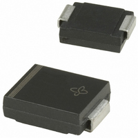
... SM15T Series Vishay General Semiconductor PACKAGE OUTLINE DIMENSIONS in inches (millimeters) DO-214AB (SMC) 0.126 (3.20) 0.114 (2.90) 0.103 (2.62) 0.079 (2.06) 0.060 (1.52) 0.030 (0.76) www.vishay.com For technical questions within your region, please contact one of the following: 4 PDD-Americas@vishay.com, PDD-Asia@vishay.com, PDD-Europe@vishay.com Cathode Band ...

Page 5

... Vishay product could result in personal injury or death. Customers using or selling Vishay products not expressly indicated for use in such applications their own risk and agree to fully indemnify and hold Vishay and its distributors harmless from and against any and all claims, liabilities, expenses and damages arising or resulting in connection with such use or sale, including attorneys fees, even if such claim alleges that Vishay or its distributor was negligent regarding the design or manufacture of the part ...

Related keywords