3N257-E4/1 Vishay, 3N257-E4/1 Datasheet - Page 3
3N257-E4/1
Manufacturer Part Number
3N257-E4/1
Description
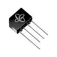
BRIDGE RECTIFIER, 1PH, 2A, 600V THD
Manufacturer
Vishay
Datasheet
1.3N253-E445.pdf
(4 pages)
Specifications of 3N257-E4/1
No. Of Phases
Single
Repetitive Reverse Voltage Vrrm Max
600V
Forward Current If(av)
2A
Forward Voltage Vf Max
1.1V
Current Rating
2A
Diode Type
Bridge Rectifier
Lead Free Status / RoHS Status
Lead free / RoHS Compliant


PACKAGE OUTLINE DIMENSIONS in inches (millimeters)
Document Number: 88532
Revision: 15-Apr-08
Figure 4. Typical Reverse Leakage Characteristics Per Diode
0.01
0.01
100
100
0.1
0.1
10
Figure 3. Typical Forward Characteristics Per Diode
10
1
1
0
0
Percent of Rated Peak Reverse Voltage (%)
0.2
Instantaneous Forward Voltage (V)
20
0.4
40
0.6
PDD-Americas@vishay.com, PDD-Asia@vishay.com, PDD-Europe@vishay.com
For technical questions within your region, please contact one of the following:
T
T
T
0.8
T
Pulse Width = 300 µs
1 % Duty Cycle
J
J
J
60
J
= 25 °C
= 125 °C
= 100 °C
= 25 °C
0.180 (4.57)
0.200 (5.08)
0.028 (0.76)
0.034 (0.86)
0.125 x 45°
1.0
DIA.
Polarity shown on front side of case: positive lead by beveled corner
(3.2)
80
2KBP005M thru 2KBP10M, 3N253 thru 3N259
1.2
(15.2)
0.60
MIN.
100
1.4
0.600 (15.24)
0.560 (14.22)
Case Style KBPM
(1.52)
0.060
0.160 (4.1)
0.140 (3.6)
0.50 (12.7) MIN.
0.460 (11.68)
0.420 (10.67)
100
10
0.105 (2.67)
0.085 (2.16)
1
Figure 5. Typical Junction Capacitance Per Diode
0.1
Vishay General Semiconductor
0.460 (11.68)
0.500 (12.70)
Reverse Voltage (V)
1
10
T
f = 1.0 MHz
V
J
sig
= 25 °C
= 50 mVp-p
www.vishay.com
100
3
Related parts for 3N257-E4/1
Image
Part Number
Description
Manufacturer
Datasheet
Request
R

Part Number:
Description:
DIODE BRIDGE 2A 600V 4SIP
Manufacturer:
Vishay
Datasheet:
Part Number:
Description:
2A,600V,GLASS,IN-LINE BRIDGE
Manufacturer:
Vishay
Datasheet:

Part Number:
Description:
357-036-542-201 CARDEDGE 36POS DL .156 BLK LOPRO
Manufacturer:
Vishay
Datasheet:
Part Number:
Description:
357-036-542-201 CARDEDGE 36POS DL .156 BLK LOPRO
Manufacturer:
Vishay
Datasheet:
Part Number:
Description:
357-036-542-201 CARDEDGE 36POS DL .156 BLK LOPRO
Manufacturer:
Vishay
Datasheet:
Part Number:
Description:
357-036-542-201 CARDEDGE 36POS DL .156 BLK LOPRO
Manufacturer:
Vishay
Datasheet:
Part Number:
Description:
357-036-542-201 CARDEDGE 36POS DL .156 BLK LOPRO
Manufacturer:
Vishay
Datasheet:
Part Number:
Description:
357-036-542-201 CARDEDGE 36POS DL .156 BLK LOPRO
Manufacturer:
Vishay
Datasheet:
Part Number:
Description:
357-036-542-201 CARDEDGE 36POS DL .156 BLK LOPRO
Manufacturer:
Vishay
Datasheet:
Part Number:
Description:
357-036-542-201 CARDEDGE 36POS DL .156 BLK LOPRO
Manufacturer:
Vishay
Datasheet:
Part Number:
Description:
357-036-542-201 CARDEDGE 36POS DL .156 BLK LOPRO
Manufacturer:
Vishay
Datasheet:
Part Number:
Description:
357-036-542-201 CARDEDGE 36POS DL .156 BLK LOPRO
Manufacturer:
Vishay
Datasheet:
Part Number:
Description:
357-036-542-201 CARDEDGE 36POS DL .156 BLK LOPRO
Manufacturer:
Vishay
Datasheet:
Part Number:
Description:
357-036-542-201 CARDEDGE 36POS DL .156 BLK LOPRO
Manufacturer:
Vishay
Datasheet:
Part Number:
Description:
357-036-542-201 CARDEDGE 36POS DL .156 BLK LOPRO
Manufacturer:
Vishay
Datasheet: