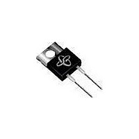
FES16DT-E3 Vishay, FES16DT-E3 Datasheet - Page 3

FES16DT-E3
Manufacturer Part Number
FES16DT-E3
Description
Diode
Manufacturer
Vishay
Datasheet
1.FES16AT-E345.pdf
(5 pages)
Specifications of FES16DT-E3
Current Rating
16A
Leaded Process Compatible
Yes
Features
Ultrafast Recovery
Forward Current If
16A
Mounting Type
Through Hole
Package / Case
TO-220AC
Diode Type
Ultrafast Recovery
Repetitive Reverse Voltage Vrrm Max
200V
Forward Current If(av)
16A
Forward Voltage Vf Max
975mV
Reverse Recovery Time Trr Max
35ns
Rohs Compliant
Yes
Lead Free Status / RoHS Status
Lead free / RoHS Compliant
Available stocks
Company
Part Number
Manufacturer
Quantity
Price
Company:
Part Number:
FES16DT-E3/45
Manufacturer:
TI
Quantity:
4 300
Company:
Part Number:
FES16DT-E3/45
Manufacturer:
Vishay Semiconductors
Quantity:
370
RATINGS AND CHARACTERISTICS CURVES
(T
Document Number: 88599
Revision: 07-Jan-08
Figure 2. Maximum Non-Repetitive Peak Forward Surge Current
A
= 25 °C unless otherwise noted)
Figure 3. Typical Instantaneous Forward Characteristics
300
250
200
150
100
100
Figure 1. Maximum Forward Current Derating Curve
0.1
20
16
12
50
10
8
4
0
0
1
0.2
1
0
T
J
= 125 °C
0.4
Instantaneous Forward Voltage (V)
Number of Cycles at 60 Hz
0.6
Case Temperature (°C)
50
0.8
T
8.3 ms Single Half Sine-Wave
JEDEC Method
J
PDD-Americas@vishay.com, PDD-Asia@vishay.com, PDD-Europe@vishay.com
Resistive or Inductive Load
= T
For technical questions within your region, please contact one of the following:
10
J
max.
1.0
T
100
J
= 25 °C
1.2
50 - 200 V
300 - 400 V
500 - 600 V
1.4
150
100
1.6
FES(F,B)16AT thru FES(F,B)16JT
1000
1000
100
100
0.1
10
10
Figure 4. Typical Reverse Leakage Characteristics
1
0.1
0
Vishay General Semiconductor
Percent of Rated Peak Reverse Voltage (%)
Figure 5. Typical Junction Capacitance
20
50 - 400 V
500 - 600 V
Reverse Voltage (V)
1
T
T
J
J
= 100 °C
40
= 25 °C
60
10
T
f = 1.0 MHz
V
J
sig
= 25 °C
= 50 mVp-p
T
50 - 200 V
300 - 400 V
J
80
= 25 °C
www.vishay.com
100
100
3


