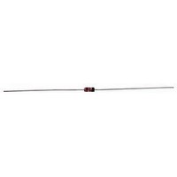
1N5240C-TAP Vishay, 1N5240C-TAP Datasheet - Page 3

1N5240C-TAP
Manufacturer Part Number
1N5240C-TAP
Description
ZENER DIODE, 500mW, 10V, DO-35
Manufacturer
Vishay
Datasheet
1.1N5240C-TAP.pdf
(7 pages)
Specifications of 1N5240C-TAP
Zener Voltage Vz Typ
10V
Power Dissipation Pd
500mW
Diode Case Style
DO-35
No. Of Pins
2
Diode Type
Zener
Termination Type
Axial Leaded
Vz Test Current, Izt
20mA
Package / Case
2-DO-35
Lead Free Status / RoHS Status
Lead free / RoHS Compliant
1)
Typical Characteristics (Tamb = 25 C unless otherwise specified)
Document Number 84613
Rev. 1.0, 02-Sep-04
Figure 2. Typical Change of Working Voltage under Operating
Based on dc-measurement at thermal equilibrium; lead length = 9.5 (3/8 "); thermal resistance of heat sink = 30 K/W
95 961 1
95 9598
Partnumber
1N5265C
1N5266C
1N5267C
1000
500
400
300
200
100
100
10
0
1
Figure 1. Thermal Resistance vs. Lead Length
0
0
T
j
=25°C
5
Nominal Zener
5
Conditions at T
@ I
Voltage
l – Lead Length ( mm )
V
Z
ZT
62
68
75
V
10
– Z-Voltage ( V )
, V
10
1)
T
Z
I
l
L
Z
=constant
=5mA
15
amb
Test Current
l
15
=25°C
20
mA
I
1.8
1.7
ZT
2
20
25
Impedance
Z
Maximum
Dynamic
ZT
185
230
270
@ I
ZT
1)
Z
Impedance
Maximum
ZK
Dynamic
95 9599
95 9602
0.25 mA
Figure 4. Total Power Dissipation vs. Ambient Temperature
1400
1600
1700
Figure 3. Typical Change of Working Voltage vs. Junction
@ I
600
500
400
300
200
100
1.3
1.2
1.1
1.0
0.9
0.8
ZK
0
1N5221C to 1N5267C
–60
0
=
V
Ztn
Temperature of
T
=V
40
amb
0
T
Coeffizient
j
Zt
– Junction Temperature (°C )
Typical
+0.097
+0.097
+0.098
/V
– Ambient T emperature(°C )
@ I
(%/K)
Z
(25°C)
ZT
60
80
Temperature
TK
Vishay Semiconductors
VZ
=10 x 10
120
120
Maximum Reverse Leakage
–4
/K
0.1
0.1
0.1
180
160
I
R
A
8 x 10
6 x 10
4 x 10
2 x 10
–2 x 10
–4 x 10
0
–4
–4
–4
–4
–4
–4
Current
/K
/K
/K
/K
240
200
/K
/K
www.vishay.com
V
47
52
56
V
R
3


