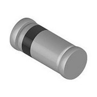
TZMC43-GS08 Vishay, TZMC43-GS08 Datasheet

TZMC43-GS08
Specifications of TZMC43-GS08
Available stocks
Related parts for TZMC43-GS08
TZMC43-GS08 Summary of contents
Page 1
... Rev. 1.5, 09-Sep-10 DiodesAmericas@vishay.com, DiodesAsia@vishay.com, Test condition Symbol ≤ 300 K/W P thJA tot I Z Test condition On PC board 1.6 mm Test condition Symbol Min 200 DiodesEurope@vishay.com TZM-Series Vishay Semiconductors 17205 Value Unit 500 tot Z Symbol Value Unit R 500 K/W thJA T 175 °C j ...
Page 2
... TZMC20 18.8 21.2 TZMC22 20.8 23.3 TZMC24 22.8 25.6 TZMC27 25.1 28.9 TZMC30 28 32 TZMC33 31 35 TZMC36 34 38 TZMC39 37 41 TZMC43 40 46 TZMC47 44 50 TZMC51 48 54 TZMC56 52 60 TZMC62 58 66 TZMC68 64 72 TZMC75 70 79 Note: Additional measurement of voltage group TZMC9V1 to TZMC75 150 ° ...
Page 3
... Zmin DiodesEurope@vishay.com TZM-Series Vishay Semiconductors Temperature Reverse leakage current coefficient of zener voltage µA µA V %/K %/K min. max. < 100 1 - 0.09 - 0.06 < ...
Page 4
... TZM-Series Vishay Semiconductors Typical Characteristics °C, unless otherwise specified amb 600 500 400 300 200 100 120 T - Ambient Temperature (°C) 95 9602 amb Figure 1. Total Power Dissipation vs. Ambient Temperature 1000 °C j 100 Z-Voltage (V) 95 9598 Z Figure 2. Typical Change of Working Voltage under Operating Conditions 25° ...
Page 5
... For technical questions within your region, please contact one of the following: Rev. 1.5, 09-Sep-10 DiodesAmericas@vishay.com, DiodesAsia@vishay.com, 1000 = 500 mW 100 = 25 ° 9606 Figure 9. Differential Z-Resistance vs. Z-Voltage = 25 °C 35 Single Pulse 0. 0. Pulse Length (ms) p Figure 10. Thermal Response DiodesEurope@vishay.com TZM-Series Vishay Semiconductors ° Z-Voltage ( 300 K/W thJA jmax amb 2 1 T/Z ) )/( thp zj 2 ...
Page 6
... TZM-Series Vishay Semiconductors Package Dimensions in millimeters (inches): Cathode indification * 3.7 (0.146) 3.3 (0.130) * The gap between plug and glass can be either on cathode or anode side Foot print recommendation: Document no.:6.560-5005.01-4 Rev Date: 07.June.2006 96 12070 Document Number 84122 For technical questions within your region, please contact one of the following: Rev ...
Page 7
... Vishay disclaims any and all liability arising out of the use or application of any product described herein or of any information provided herein to the maximum extent permitted by law. The product specifications do not expand or otherwise modify Vishay’ ...


