CM150DY-12NF Powerex Inc, CM150DY-12NF Datasheet - Page 3
CM150DY-12NF
Manufacturer Part Number
CM150DY-12NF
Description
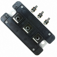
IGBT Module
Manufacturer
Powerex Inc
Series
IGBTMOD™r
Type
IGBT Moduler
Datasheet
1.CM150DY-12NF.pdf
(4 pages)
Specifications of CM150DY-12NF
Power Dissipation Pd
590W
Collector Emitter Voltage V(br)ceo
600V
Continuous Collector Current Ic
150A
Collector Emitter Saturation Voltage Vce(sat)
2.2V
Current Rating
150A
Leaded Process Compatible
Yes
Configuration
Half Bridge
Voltage - Collector Emitter Breakdown (max)
600V
Vce(on) (max) @ Vge, Ic
2.2V @ 15V, 150A
Current - Collector (ic) (max)
150A
Current - Collector Cutoff (max)
1mA
Input Capacitance (cies) @ Vce
23nF @ 10V
Power - Max
590W
Input
Standard
Ntc Thermistor
No
Mounting Type
Chassis Mount
Package / Case
Module
Prx Availability
RequestQuote
Distributorinventory
View
Voltage
600V
Current
150A
Circuit Configuration
Dual
Rohs Compliant
Yes
Recommended Gate Driver
VLA504
Recommended Dc To Dc Converter
VLA106-15242 or VLA106-24242
Interface Circuit Ref Design
BG2C-3015
Lead Free Status / RoHS Status
Lead free / RoHS Compliant
For Use With
BG2B-5015 - KIT DEV BOARD 2CN 5A FOR IGBTBG2B-3015 - KIT DEV BOARD 2CN 3A FOR IGBTBG2B-1515 - KIT DEV BOARD 1.5A FOR IGBTBG2A-NF - KIT DEV BOARD FOR IGBT
Igbt Type
-
Lead Free Status / RoHS Status
Lead free / RoHS Compliant, Lead free / RoHS Compliant
Other names
835-1009
Available stocks
Company
Part Number
Manufacturer
Quantity
Price
Company:

Part Number:
CM150DY-12NF
Manufacturer:
Powerex Inc
Quantity:
135
Company:
Part Number:
CM150DY-12NF
Manufacturer:
IXYS
Quantity:
492
Part Number:
CM150DY-12NF
Manufacturer:
MITSUBISHI/三菱
Quantity:
20 000
Part Number:
CM150DY-12NF
Quantity:
55


Powerex, Inc., 200 E. Hillis Street, Youngwood, Pennsylvania 15697-1800 (724) 925-7272
CM150DY-12NF
Dual IGBTMOD™ NF-Series Module
150 Amperes/600 Volts
Thermal and Mechanical Characteristics, T
Characteristics
Thermal Resistance, Junction to Case
Thermal Resistance, Junction to Case
Thermal Resistance, Junction to Case
Contact Thermal Resistance
External Gate Resistance
300
250
200
150
100
10
10
10
50
0
3
2
1
0
0
V
COLLECTOR-EMITTER VOLTAGE, V
EMITTER-COLLECTOR VOLTAGE, V
GE
20V
=
FORWARD CHARACTERISTICS
OUTPUT CHARACTERISTICS
T
T
2
1
j
j
= 25°C
= 125°C
FREE-WHEEL DIODE
13
15
(TYPICAL)
(TYPICAL)
2
4
6
3
8
CE
EC
T
, (VOLTS)
, (VOLTS)
j
8
4
= 25
12
11
10
9
o
C
10
5
R
R
R
Symbol
R
th(j-c)
th(j-c)
th(j-c)
th(c-f)
R
10
10
10
10
G
-1
0
2
1
0
4
3
2
1
'Q
10
Q
D
SATURATION VOLTAGE CHARACTERISTICS
0
-1
COLLECTOR-EMITTER VOLTAGE, V
V
V
j
GE
GE
COLLECTOR-CURRENT, I
= 25 C unless otherwise specified
Per 1/2 Module, Thermal Grease Applied
50
= 15V
= 0V
T
T
Per FWDi 1/2 Module, T
Per IGBT 1/2 Module, T
j
j
CAPACITANCE VS. V CE
COLLECTOR-EMITTER
= 25°C
= 125°C
T
C
100
10
Point per Outline Drawing
Point per Outline Drawing
Reference Point Under Chips
0
(TYPICAL)
(TYPICAL)
Per IGBT 1/2 Module,
150
Test Conditions
200
C
10
, (AMPERES)
1
C
C
C
CE
oes
ies
res
250
, (VOLTS)
C
C
Reference
300
10
Reference
2
10
10
10
10
10
8
6
4
2
0
3
2
1
0
10
SATURATION VOLTAGE CHARACTERISTICS
6
T
1
Min.
4.2
j
—
—
—
—
= 25°C
GATE-EMITTER VOLTAGE, V
COLLECTOR CURRENT, I
SWITCHING CHARACTERISTICS
8
COLLECTOR-EMITTER
10
HALF-BRIDGE
0.07
Typ.
—
—
—
—
(TYPICAL)
(TYPICAL)
12
10
2
I
I
I
14
C
C
C
= 300A
= 150A
= 60A
t
t
t
t
f
d(off)
C
d(on)
r
Max.
V
V
R
T
Inductive Load
0.21
0.47
0.16
, (AMPERES)
j
—
42
CC
GE
G
GE
16
= 125°C
= 4.2
, (VOLTS)
= 300V
= ±15V
18
Units
C/W
C/W
C/W
C/W
10
20
3
3
Related parts for CM150DY-12NF
Image
Part Number
Description
Manufacturer
Datasheet
Request
R

Part Number:
Description:
IGBT MOD DUAL 1200V 150A H SER
Manufacturer:
Powerex Inc
Datasheet:

Part Number:
Description:
IGBT MOD DUAL 600V 150A H SER
Manufacturer:
Powerex Inc
Datasheet:

Part Number:
Description:
IGBT MOD DUAL 1200V 150A A SER
Manufacturer:
Powerex Inc
Datasheet:

Part Number:
Description:
IGBT MOD DUAL 1400V 150A H SER
Manufacturer:
Powerex Inc
Datasheet:
Part Number:
Description:
Transistors
Manufacturer:
Powerex Inc
Datasheet:
Part Number:
Description:
IGBT Module
Manufacturer:
Powerex Inc
Datasheet:
Part Number:
Description:
IGBT MODULE A-SERIES DUAL DP 1700 150
Manufacturer:
Powerex Inc
Datasheet:
Part Number:
Description:
Manufacturer:
Powerex Inc
Datasheet:
Part Number:
Description:
Manufacturer:
Powerex Inc
Datasheet:
Part Number:
Description:
Manufacturer:
Powerex Inc
Datasheet:
Part Number:
Description:
Manufacturer:
Powerex Inc
Datasheet:
Part Number:
Description:
Manufacturer:
Powerex Inc
Datasheet:
Part Number:
Description:
Manufacturer:
Powerex Inc
Datasheet:
Part Number:
Description:
Manufacturer:
Powerex Inc
Datasheet:
Part Number:
Description:
Manufacturer:
Powerex Inc
Datasheet: