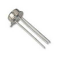
VP0808B-E3 Vishay, VP0808B-E3 Datasheet

VP0808B-E3
Specifications of VP0808B-E3
Related parts for VP0808B-E3
VP0808B-E3 Summary of contents
Page 1
... Substrate and Case Logic Switch OFF Logic “0” Logic “0” 0.8 V 0.8 V Logic “1” Logic “1” 2 DG180/181/182 Vishay Siliconix Audio Switching Video Switching Sample/Hold Guidance and Control Systems Aerospace V– V– IN Metal Can Top View www.vishay.com FaxBack 408-970-5600 4-1 ...
Page 2
... R IN Current ( DG180 . . . . . . . . . . . . . . . . . . . . . . . . . . . . . . . . . . . . . www.vishay.com FaxBack 408-970-5600 4-2 Package Part Number 10-Pin Metal Can DG181BA 14-Pin Sidebraze DG180BP ...
Page 3
... Min Max Min Max Unit –7.5 15 –7 1000 300 10 15 1000 300 1000 300 10 15 1000 300 –2 –10 –200 –200 –250 –250 400 600 ns ns 200 250 pF dB 1.5 1.5 –5 – 4.5 4.5 –2 –2 www.vishay.com FaxBack 408-970-5600 4-3 ...
Page 4
... The algebraic convention whereby the most negative value is a minimum and the most positive a maximum, is used in this data sheet. e. Guaranteed by design, not subject to production test input voltage to perform proper function. IN www.vishay.com FaxBack 408-970-5600 4-4 Test Conditions Unless Specified V– = – Temp ...
Page 5
... Max Unit –10 15 – 100 150 150 1 5 100 100 1 5 100 100 100 100 1 5 100 100 –2 –10 –200 –200 –250 –250 250 300 ns ns 130 150 1.5 1.5 –5 – 4.5 4.5 –2 –2 www.vishay.com FaxBack 408-970-5600 4-5 ...
Page 6
... S 1 –50 – Temperature ( C) Leakage vs. Temperature (DG180) 100 V– = – S(off D(on) 0 Temperature ( C) www.vishay.com FaxBack 408-970-5600 4-6 100 –I– 105 125 –55 –35 Switching Time vs. V 230 210 190 170 150 130 110 90 75 100 125 –55 Switching Time vs. V 130 ...
Page 7
... S-52895—Rev. D, 16-Jun- Suffix 14 10 105 125 (DG181/182) 100 D(on S(off DG180/181/182 Vishay Siliconix Capacitance vs (DG180 MHz C S(off) C D(on) C D(off) –8 – – Drain or Source Voltage ( Off Isolation vs. Frequency DG181/182 DG180 V– = – 220 mV IN RMS – Frequency (Hz) www.vishay.com FaxBack 408-970-5600 8 4-7 ...
Page 8
... DG180 10 –20 DG181 12 – –15 DG182 10 –20 12 –12 Notes: a. Application Hints are for DESIGN AID ONLY, not guaranteed and not subject to production testing. b. Electrical Parameter Chart based www.vishay.com FaxBack 408-970-5600 4 Logic Input 100 Switch Output – DS(on) FIGURE 2. Switching Time ...
Page 9
... Vishay disclaims any and all liability arising out of the use or application of any product described herein or of any information provided herein to the maximum extent permitted by law. The product specifications do not expand or otherwise modify Vishay’ ...


