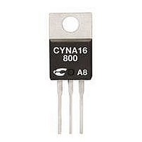
CYNB55-800 C3 SEMI, CYNB55-800 Datasheet

CYNB55-800
Manufacturer Part Number
CYNB55-800
Description
SCR THYRISTOR, 35A, 800V, TO-220AB
Manufacturer
C3 SEMI
Datasheet
1.CYNB55-1000.pdf
(2 pages)
Specifications of CYNB55-800
Gate Trigger Current Max, Igt
35mA
Peak Reflow Compatible (260 C)
Yes
Thermal Resistance, Junction-case
1°C/W
Thermal Resistance
60°C/W
Peak Surge Current
700A
Di/dt
100A/µs
Lead Free Status / RoHS Status
Lead free / RoHS Compliant
TO-220AB Non-Isolated
Applications
• Motor Control
• Overvoltage Crowbar Protection
• Capacitive Discharge Ignition
• Voltage Regulation
• Welding Equipment
• Capacitive Filter Soft Start
ISO9001 Certified
K
(CYNB55)
A
(Inrush Current Control)
G
G
A
K
A
C3 Semiconductor, LLC
Absolute Maximum Ratings
RMS On-State Current (full sine wave)
Average On-State Current
Non Repetitive Surge Peak On-State Current
(Full Cycle, Tj Initial = 25
I
Critical rate of rise of on-state current
I
Peak Gate Current @ T
Average Gate Power Dissipation @ Tj = 125
S
O
M
Electrical Characteristics
I
V
V
I
I
dv/dt MIN @ V
V
I
I
GENERAL NOTES
2
G
GT
H
L
DRM
RRM
1. Not intented for continuous current use above 50A
2. All parameters at 25 degrees C unless otherwise specified.
o t
GT
GD
TM
p
t
=2 x I
x a
MAX @ I
MAX @ I
Continuous use obove 50A
r e
a V
a r
MAX @ V
MAX @ V
MIN @ V
m i
MAX @ I
i t a
MAX @ V
MAX @ V
e g
u l
u
GT
f e
g n
m
e T
r o
, tr<100 ns, T
J
P
m
G
T
n u
e
u f
e p
= 1.2 I
D
=
k a
D
TM
>
>
>
D
i t c
i s
=12 V, R
D
DRM =
5
DRM =
=V
a r
=12 V, R
0 0
R
Suitable for General Purpose AC Switching
IGT 35mA Max.
VDRM/VRMM 400, 600, 800, 1000V
g n
= 67%V
=
n o
u t
v e
DRM
8 7
m
GT
e r
e T
r e
RMS
V
A
, A
V
, R
R
e s
RRM
m
RRM
j
L
(
may exceed PCB solder melting temperatures.
j
L
n a
a g
p t
= 125
= 125
e p
= 30Ω
DRM
˚
L
= 30Ω
G
) C
= 3.3kΩ
e g
=
e t
a r
a
e t
3
o
(
u t
˚
0 8
˚
a g
C
e p
C
o V
e r
s µ
e t
) n
a t l
R
o
n a
e g
NOTE 2
e p
RMS
e g
) n
NOTE 1
(Fig 2); for high surge conditions only,
˚
C
Tc = 70
Tc = 70
Tj = 125
T
T
T
T
= j
= j
= j
= j
1
5 2
5 2
1
5 2
5 2
C ˚
C ˚
˚
°
˚
C ˚
C ˚
C
C
C
TO-220AB
CONDITIONS
p t
TO-220AB
p t
F = 50 Hz
F
=
=
=
0 6
0 1
0 2
55Amp - 400/600/800/1000V -
z H
m
s µ
s
0 1
SYMBOL
P
I
35mA
0 5
90mA
T(RMS)
I
V
I
G
0 0
4
di/dt
1.3V
. 0
. 1
µ 5
T(AV)
I
T
I
TSM
RGM
2
GM
m
T
A (
stg
m
V 2
V 6
t
/ V
j
A
A
CYNB55
A
) V
s µ
-40 to +150
-40 to +125
RATING
2030A
100A/µs
675A
700A
55A
35A
1
4A
5V
W
2
SCR
s
˚
˚
C
C
Related parts for CYNB55-800
CYNB55-800 Summary of contents
Page 1
... D DRM = µ ˚ ˚ DRM = RRM ˚ DRM = RRM (Fig 2); for high surge conditions only, RMS may exceed PCB solder melting temperatures. RMS CYNB55 55Amp - 400/600/800/1000V - SCR CONDITIONS SYMBOL RATING TO-220AB I 55A T(RMS) I TO-220AB 35A T(AV 675A I TSM 700A 2030A 2 s di/dt 100A/µ ...
Page 2
... For recommended applications and more information contact: For recommended applications and more information contact: USA : Sales Support USA : Sales Support (888) 882-8689 C3 Semiconductors, LLC. 2320 Paseo de las Americas, Ste. 104, San Diego, CA 92154 Email : sales@c3semi.com WEB SITE: http://www.C3semi.com CYNB55 55Amp - 400/600/800/1000V - SCR SYMBOL RATING ˚ ...


