31DQ10GTR Vishay, 31DQ10GTR Datasheet - Page 2
31DQ10GTR
Manufacturer Part Number
31DQ10GTR
Description
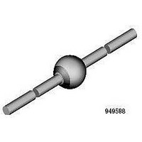
RECTIFIER DIODE,SCHOTTKY,100V V(RRM),Axial-10
Manufacturer
Vishay
Datasheet
1.31DQ09G.pdf
(6 pages)
Specifications of 31DQ10GTR
Product
Schottky Rectifiers
Peak Reverse Voltage
100 V
Forward Continuous Current
3.3 A
Max Surge Current
370 A
Configuration
Single
Forward Voltage Drop
0.97 V at 6 A
Maximum Reverse Leakage Current
100 uA
Operating Temperature Range
- 40 C to + 150 C
Mounting Style
Through Hole
Package / Case
C-16
Lead Free Status / RoHS Status
Lead free / RoHS Compliant


Document Number: 93322
31DQ09G, 31DQ10G
Bulletin PD-20806 11/05
Voltage Ratings
Absolute Maximum Ratings
Electrical Specifications
Thermal-Mechanical Specifications
V
I
C
L
dv/dt Max. Voltage Rate of Change
T
T
R
R
wt
I
I
E
I
V
V
RM
F(AV)
FSM
AR
S
FM
J
stg
T
thJA
thJL
AS
R
RWM
Max. Forward Voltage Drop
* See Fig. 1
Max. Reverse Leakage Current
* See Fig. 2
Typical Junction Capacitance
Typical Series Inductance
Approximate Weight
Part number
Max. DC Reverse Voltage (V)
Max. Working Peak Reverse Voltage (V)
Parameters
Parameters
Max. Junction Temperature Range
Max. Storage Temperature Range
Max. Thermal Resistance Junction
to Ambient
Typical Thermal Resistance Junction
to Lead
Case Style
Marking Device
Max. Average Forward Current
* See Fig. 4
Max. Peak One Cycle Non-Repetitive
Surge Current * See Fig. 6, T
Non-Repetitive Avalanche Energy
Repetitive Avalanche Current
Parameters
J
= 25°C
(1)
(1)
31DQ..
1.2 (0.042) g (oz.)
370
-40 to 150
-40 to 150
3.0
3.3
0.5
60
31DQ.. Units
31DQ.. Units
10000
0.85
0.97
0.69
0.80
110
0.1
9.0
80
34
31DQ10G
3
C - 16
Units
mJ
A
A
A
°C/W DC operation
°C/W DC operation
V/µs (Rated V
mA
mA
nH
pF
°C
°C
V
V
V
V
T
50% duty cycle @ T
5µs Sine or 3µs Rect. pulse
10ms Sine or 6ms Rect. pulse
Current decaying linearly to zero in 1 µsec
Frequency limited by T
J
@ 3A
@ 6A
@ 3A
@ 6A
T
T
V
Measured lead to lead 5mm from package body
Without cooling fins
31DQ09G
= 25 °C, I
J
J
R
= 25 °C
= 125 °C
= 5V
90
DC
R
)
AS
(test signal range 100Khz to 1Mhz) 25°C
Conditions
Conditions
Conditions
= 1.0 Amps, 18 µs square pulse
(1) Pulse Width < 300µs, Duty Cycle <2%
V
T
T
J
J
R
C
= 25 °C
= 125 °C
= rated V
= 53.4°C, rectangular wave form
J
max. V
A
R
Following any rated
load condition and with
rated V
= 1.5 x V
31DQ10G
www.vishay.com
100
RRM
R
typical
applied
2
Related parts for 31DQ10GTR
Image
Part Number
Description
Manufacturer
Datasheet
Request
R

Part Number:
Description:
DIODE SCHOTTKY 100V 3.3A C-16
Manufacturer:
Vishay
Datasheet:

Part Number:
Description:
357-036-542-201 CARDEDGE 36POS DL .156 BLK LOPRO
Manufacturer:
Vishay
Datasheet:
Part Number:
Description:
357-036-542-201 CARDEDGE 36POS DL .156 BLK LOPRO
Manufacturer:
Vishay
Datasheet:
Part Number:
Description:
357-036-542-201 CARDEDGE 36POS DL .156 BLK LOPRO
Manufacturer:
Vishay
Datasheet:
Part Number:
Description:
357-036-542-201 CARDEDGE 36POS DL .156 BLK LOPRO
Manufacturer:
Vishay
Datasheet:
Part Number:
Description:
357-036-542-201 CARDEDGE 36POS DL .156 BLK LOPRO
Manufacturer:
Vishay
Datasheet:
Part Number:
Description:
357-036-542-201 CARDEDGE 36POS DL .156 BLK LOPRO
Manufacturer:
Vishay
Datasheet:
Part Number:
Description:
357-036-542-201 CARDEDGE 36POS DL .156 BLK LOPRO
Manufacturer:
Vishay
Datasheet:
Part Number:
Description:
357-036-542-201 CARDEDGE 36POS DL .156 BLK LOPRO
Manufacturer:
Vishay
Datasheet:
Part Number:
Description:
357-036-542-201 CARDEDGE 36POS DL .156 BLK LOPRO
Manufacturer:
Vishay
Datasheet:
Part Number:
Description:
357-036-542-201 CARDEDGE 36POS DL .156 BLK LOPRO
Manufacturer:
Vishay
Datasheet:
Part Number:
Description:
357-036-542-201 CARDEDGE 36POS DL .156 BLK LOPRO
Manufacturer:
Vishay
Datasheet:
Part Number:
Description:
357-036-542-201 CARDEDGE 36POS DL .156 BLK LOPRO
Manufacturer:
Vishay
Datasheet:
Part Number:
Description:
357-036-542-201 CARDEDGE 36POS DL .156 BLK LOPRO
Manufacturer:
Vishay
Datasheet:
Part Number:
Description:
357-036-542-201 CARDEDGE 36POS DL .156 BLK LOPRO
Manufacturer:
Vishay
Datasheet: