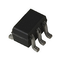
HSMS-286P-TR2G Avago Technologies US Inc., HSMS-286P-TR2G Datasheet - Page 10

HSMS-286P-TR2G
Manufacturer Part Number
HSMS-286P-TR2G
Description
Bridge/Ring Diode Array,SOT-363
Manufacturer
Avago Technologies US Inc.
Datasheet
1.HSMS-286P-TR2G.pdf
(18 pages)
Specifications of HSMS-286P-TR2G
Diode Type
Schottky - 2 Pair Series Connection
Voltage - Peak Reverse (max)
4V
Capacitance @ Vr, F
0.25pF @ 0V, 1MHz
Package / Case
SC-70-6, SC-88, SOT-363
Pin Count
6
Lead Free Status / RoHS Status
Lead free / RoHS Compliant
Current - Max
-
Power Dissipation (max)
-
Resistance @ If, F
-
Lead Free Status / Rohs Status
Compliant
HSMS-285X fig 11 was 7
As was the case at 2.45 GHz, the circuit is entirely dis‑
tributed element, both low cost and compact. Input
impedance for this network is given in Figure 22.
Figure 22. Input Impedance.
Input return loss, shown in Figure 23, exhibits wideband
match.
Figure 23. Input Return Loss.
Voltage Doublers
To this point, we have restricted our discus sion to
single diode detectors. A glance at Figure 9, however,
will lead to the suggestion that the two types of single
diode detectors be combined into a two diode voltage
doubler
detector is shown in Figure 24.
Figure 24. Voltage Doubler Circuit.
10
RF IN
[4]
-10
-15
-20
-5
0
FREQUENCY (GHz): 5.6-6.0
5.6
(known also as a full wave rectifier). Such a
HSMS-0005 fig 26 was 23
NETWORK
Z-MATCH
HSMS-285X fig 27 was 24
5.7
FREQUENCY (GHz)
5.8
VIDEO OUT
5.9
6.0
Such a circuit offers several advantages. First the voltage
outputs of two diodes are added in series, increasing
the overall value of voltage sensitivity for the network
(compared to a single diode detector). Second, the RF
impedances of the two diodes are added in parallel,
making the job of reactive matching a bit easier. Such a
circuit can easily be realized using the two series diodes
in the HSMS‑286C.
The “Virtual Battery”
The voltage doubler can be used as a virtual battery,
to provide power for the operation of an I.C. or a tran‑
sistor oscillator in a tag. Illuminated by the CW signal
from a reader or inter rogator, the Schottky circuit will
produce power sufficient to operate an I.C. or to charge
up a capacitor for a burst transmis sion from an oscilla‑
tor. Where such virtual batteries are employed, the bulk,
cost, and limited lifetime of a battery are eliminated.
Temperature Compensation
The compression of the detector’s transfer curve is
beyond the scope of this data sheet, but some general
comments can be made. As was given earlier, the diode’s
video resistance is given by
where T is the diode’s temperature in °K.
As can be seen, temperature has a strong effect upon R
and this will in turn affect video bandwidth and input
RF impedance. A glance at Figure 6 suggests that the
proper choice of bias current in the HSMS‑286x series
can minimize variation over temperature.
The detector circuits described earlier were tested
over temperature. The 915 MHz voltage doubler using
the HSMS‑286C series produced the output voltages
as shown in Figure 25. The use of 3 µA of bias resulted
in the highest voltage sensitivity, but at the cost of a
wide variation over temperature. Dropping the bias to
1 µA produced a detector with much less temperature
variation.
A similar experiment was conducted with the HSMS‑
286B series in the 5.8 GHz detector. Once again, reducing
the bias to some level under 3 µA stabilized the output
of the detector over a wide temperature range.
It should be noted that curves such as those given in
Figures 25 and 26 are highly dependent upon the exact
design of the input impedance matching network. The
designer will have to experiment with bias current using
his specific design.
R
V
=
8.33 x 10
I
S
+ I
b
‑5
nT
V
,


