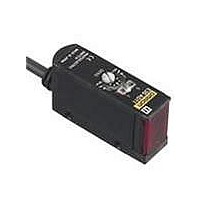
E3S-AD83 Omron, E3S-AD83 Datasheet - Page 9

E3S-AD83
Manufacturer Part Number
E3S-AD83
Description
10CM DIFF PNP VERT
Manufacturer
Omron
Type
Photoelectric Sensorr
Series
E3S-Ar
Datasheet
1.E3S-AT61.pdf
(27 pages)
Specifications of E3S-AD83
Features
Light ON / Dark ON
Height
21 mm
Length
45.3 mm
Maximum Operating Temperature
+ 55 C
Minimum Operating Temperature
- 25 C
Operating Supply Voltage
10 V to 30 V
Width
12.4 mm
Sensing Distance
100 mm
Output Configuration
PNP
Sensing Method
Reflective, Diffuse
Sensing Object
White Paper
Sensing Light
Infrared
Mounting Type
Bracket Mount, Vertical
Current - Supply
35mA
Voltage - Supply
10 V ~ 30 V
Package / Case
Module, Pre-Wired
Lead Free Status / RoHS Status
Lead free / RoHS Compliant
Lead Free Status / RoHS Status
Lead free / RoHS Compliant
Structure of Sensor I/O Connector
Adjustment Methods
Sensitivity Adjustment for Diffuse-reflective Sensors Set to Light ON
Unlike conventional Photoelectric Sensors, the variation in the sensitivity of E3S-A Photoelectric Sensors is minimal. This means
the sensitivity can be adjusted on only a single Photoelectric Sensor, and then the adjusters on the other Photoelectric Sensors
can be set to the same scale position. There is no need to adjust the sensitivity of each Photoelectric Sensor individually.
E3S-AR41
E3S-AR91
1) Position A
2) Position B
3) Setting
1
Model
Item
2
4
3
Terminal No.
Photoelectric
Sensor
Photoelectric
Sensor
1
2
3
4
Operation
Sensing condition
Light-ON
Dark-ON
mode
Sensing object
http://www.ia.omron.com/
Sensing object
XS2F-D421-DC0-A
---
Light indicator
(red)
Load
(e.g., relay)
Light indicator
(red)
Load
(e.g., relay)
Output
transistor
Output
transistor
No incident light
T: OFF-delay timer (0 to 100 ms)
No incident light
T: OFF-delay timer (0 to 100 ms)
Backg-
round
object
Backg-
round
object
Incident light
Incident light
Timing charts
Operate
Operate
Reset
Reset
OFF
OFF
Sensitivity adjuster
OFF
OFF
ON
ON
ON
ON
(Between brown and black)
(Between blue and black)
Min.
Min.
Min.
(A)
(A)
T
T
Brown
Blue
Black
Max.
(C)
Max.
Max.
(C)
(B)
Note: Pin 2 is not used.
Classification
L Side
(LIGHT ON)
D Side
(DARK ON)
For DC
selector
switch
Mode
ON → OFF
ON → OFF
indicator
indicator
Stability
Stability
(green)
(green)
indicator
Stability
(green)
ON
Indicators
Retro-reflective Sensors
Light
indica-
tor
(red)
Wire color
Brown
Black
ON → OFF
(c)Copyright OMRON Corporation 2008 All Rights Reserved.
Blue
OFF → ON
ON → OFF
---
indicator
indicator
indicator
Stability
indicator
(green)
Light
(red)
Light
(red)
Light
(red)
Photo-
electric
Sensor
main
circuit
4.4 K
Connection Pin No.
Locate a sensing object at the sensing
distance, set the sensitivity adjuster to
the minimum scale position, and
gradually increase sensitivity by turning
the sensitivity adjuster clockwise until the
incident light indicator
Position A is where the indicator has
turned ON.
Position B is when the sensing object is
removed and the sensitivity adjuster is
turned clockwise until the incident light
indicator
where the adjuster is turned
counterclockwise (reducing the
sensitivity) from position B until the
incident light indicator
When there are no background objects,
the maximum sensitivity is position C.
Set the sensitivity adjuster to halfway
between (A) and (C) (at the optimum
sensitivity). Check that the stability
indicator
according to whether the sensing object
is there or not. There is not sufficient
margin if it does not turn ON. If this is the
case, reconsider the detection method.
Output circuit
Z
D
1
2
3
4
100 mA max.
(red
(green
Z
50 mA
max.
D
LED) is ON. Position C is
Procedure
LED) turns ON
Orange
Black
Brown
Pink
Blue
(Control
output)
(relay)
Load
(red
(red
Application
(Self-diagnostic
output)
(External
diagnostic input)
Output
(relay)
LED) is OFF.
LED) is ON.
Load
0 V
+V
---
E3S-A
10 to
30 VDC
9


