10-2J09.1062 EAO, 10-2J09.1062 Datasheet
10-2J09.1062
Specifications of 10-2J09.1062


Related parts for 10-2J09.1062


10-2J09.1062 Summary of contents
Page 1
... EAO – Your Expert Partner for Human Machine Interfaces EAO Product Information Series 51 ...
Page 2
...
Page 3
Switches and Indicators 51 ...
Page 4
... Contents Description ...................................................................................................... 3 Product Assembly .......................................................................................... 4 Devices raised mounting ............................................................................... 7 Devices flush mounting ............................................................................... 13 Accessories................................................................................................... 21 Technical Data............................................................................................... 33 Typical Applications ..................................................................................... 36 Application guidelines.................................................................................. 37 Marking .......................................................................................................... 38 Drawings........................................................................................................ 40 Index............................................................................................................... 58 2 01.2010 51 ...
Page 5
... Spare keys (Index D) for standard locks may be ordered by quoting Typ-Nr. 31-989.xxx (please state the lock number). Specimen order 0 Indicator : - Indicator actuator mm, soldering terminal Essential accessories : - Lens plastic blue, transparent, flush Single-LED MG, 24 VAC/DC, blau 4 We reserve the right to modify technical data All dimensions 31-040.005 31-903.6 10-2J12.1066 3 01.2010 ...
Page 6
... Product Assembly Indicator round, raised mounting Illuminated pushbutton, raised mounting 01.2010 1 Lens 2 LED 3 Indicator housing 4 Sealing 5 Front plate 6 Fixing nut 1 Lens 2 LED 3 Switch housing 4 Sealing 5 Front plate 6 Fixing nut 51 ...
Page 7
... Product Assembly Keylock switch round, flush mounting Actuator housing 2 Front bezel 3 Sealing 4 Front plate 5 Anti-twist ring 6 Thrust piece 7 Fixing nut 8 Switching element 51 5 01.2010 ...
Page 8
... Product Assembly Selector switch square, flush mounting 01.2010 1 Actuator housing 2 LED 3 Actuator housing 4 Front bezel 5 Sealing 6 Front plate 7 Fixing bracket 8 Fixing nut 51 ...
Page 9
... Component layout from page 40, Mounting dimensions from page 41, Technical drawing from page 42, Circuit drawing from page Typ-Nr. Typ-Nr 51-703.006 51-701.006 51-704.006 51-702.006 - S 51-050.005 51-040.005 S1 51-050.002 51-040.002 UT 51-051.006 51-041.006 51 Ø Typ-Nr. 51-741.006 0.006 51-742.006 0.006 51-030.005 0.004 51-030.002 0.004 51-031.006 0.005 7 01.2010 ...
Page 10
... 13 58 0.007 51-471.036 0.007 51-431.036 0.007 51-747.0292 0.008 51-743.0292 0.008 51-748.0292 0.008 51-744.0292 0.008 51-271.0252 0.006 51-271.022 0.006 51-131.0252 0.006 51-131.022 0.006 51-749.0292 0.010 51-745.0292 0.010 51-750.0292 0.010 51-746.0292 0.010 51-272.0252 0.008 51-132.0252 0.008 51-273.0252 0.010 51-133.0252 0.010 51-274.0252 0.012 51-134.0252 0.012 ...
Page 11
... 51-407.036D 51-417.036D 0.017 51-401.036D 51-411.036D 0.017 0.016 0.016 0.016 51-295.022D 51-235.022D 0.016 51-395.022D 51-335.022D 0.016 51-195.022D 51-135.022D 0.016 0.016 0.016 0.016 0.016 0.016 0.016 0.016 0.016 0.016 51-428.036D 51-438.036D 0.017 51-427.036D 51-437.036D 0.017 0.016 51-495.022D 51-141.022D 0.016 0.016 0.016 0.016 9 01.2010 51 e ...
Page 12
... Other lock numbers on request Switching system Snap-action switching element Contacts Normally closed Normally open Switching action Maintained action Momentary action Terminals Soldering terminal (also pluggable 2.8 x 0.5 mm) Mounting dimensions from page 41, Technical drawing from page 42, Circuit drawing from page 47 10 01.2010 Typ-Nr. Typ-Nr. ...
Page 13
... 19 40 0.008 52-748.0292 0.008 52-271.0252 0.006 52-271.022 0.006 52-749.0292 0.010 52-750.0292 0.010 52-272.0252 0.006 52-273.0252 0.006 52-274.0252 0.006 0.007 0.007 0.007 0.007 0.007 52-743.0292 0.008 52-744.0292 0.008 52-131.0252 0.006 52-131.022 0.006 52-745.0292 0.010 52-746.0292 0.010 52-132.0252 0.006 52-133.0252 0.006 52-134.0252 0.006 11 01.2010 ...
Page 14
... Switching system Snap-action switching element Contacts Normally closed Normally open Switching action Maintained action Momentary action Terminals Soldering terminal (also pluggable 2.8 x 0.5 mm) Mounting dimensions from page 41, Technical drawing from page 42, Circuit drawing from page 47 12 01.2010 MA-0-MA S1 52-571.022A M-0-MA S1 52-574.022A MA-0-M S1 52-573.022A M-0-M S1 52-572 ...
Page 15
... Continuation see next page Indicator actuator, flush mounting Terminals Soldering terminal Soldering terminal (also pluggable 2.8 x 0.5 mm Universal terminal Component layout from page 40, Mounting dimensions from page 41, Technical drawing from page 42, Circuit drawing from page dia Typ-Nr. 51-050.005F 0.004 S1 51-050.002F 0.004 UT 51-051.006F 0.005 13 01.2010 ...
Page 16
... MA UT 51-485.036F M UT 51-455.036F 51-482.036F M UT 51-452.036F 51-481.036F M UT 51-451.036F Typ-Nr 0.006 0.006 0.006 0.006 0.006 0.006 0.006 0.006 0.006 0.006 51-281.0252F 0.005 51-281.022F 0.007 51-151.0252F 0.005 51-151.022F 0.007 51-282.0252F 0.008 51-152.0252F 0.008 51-283.0252F 0.010 51-153.0252F 0.010 51-284.0252F 0.012 51-154.0252F 0.012 ...
Page 17
... S A 51-146.025D2F S A 51-147.025D2F S A 51-148.025D2F Continuation see next page 51 Ø Typ-Nr 0.027 0.027 0.027 0.027 0.027 0.027 0.027 0.027 0.027 0.027 0.027 0.027 0.027 0.027 0.027 0.027 0.027 0.027 0.027 0.027 0.027 0.027 0.027 0.027 0.027 0.027 0.027 0.027 15 01.2010 ...
Page 18
... Front : Plastic black Position A : Basic position Position C : Momentary action 2 NO Standard lock 311 Front : Plastic black Position A : Basic position Position C : Maintained action Standard lock 311 Front : Plastic black 01.2010 Typ-Nr. Typ-Nr. 51-405.036DF C 51-408.036DF 51-402.036DF 51-404.036DF C 51-407.036DF 51-401.036DF A 51-295.025D2F C 51-395.025D2F 51-195.025D2F S1 A 51-295.022DF C 51-395 ...
Page 19
... Terminals Universal terminal Soldering terminal Soldering terminal (also pluggable 2.8 x 0.5 mm) Component layout from page 40, Mounting dimensions from page 41, Technical drawing from page 42, Circuit drawing from page Typ-Nr. Typ-Nr Ø Typ-Nr. 51-438.036DF 0.026 51-437.036DF 0.026 51-141.025D2F 0.026 51-141.022DF 0.026 51-142.025D2F 0.026 51-143.025D2F 0.026 51-144.025D2F 0.026 17 01.2010 ...
Page 20
... Other lock numbers on request Switching system Snap-action switching element Contacts Normally closed Normally open Switching action Maintained action Momentary action Terminals Soldering terminal (also pluggable 2.8 x 0.5 mm) Mounting dimensions from page 41, Technical drawing from page 42, Circuit drawing from page 47 18 01.2010 Typ-Nr. Typ-Nr. ...
Page 21
... MA UT 52-476.036 52-473.036 52-475.036 52-472.036 52-471.036 52-271.0252 S1 52-271.022 52-272.0252 52-273.0252 52-274.0252 52-436.036 52-433.036 52-435.036 52-432.036 52-431.036 52-131.0252 S1 52-131.022 52-132.0252 52-133.0252 52-134.0252 0.007 0.007 0.007 0.007 0.007 0.006 0.006 0.006 0.006 0.006 0.007 0.007 0.007 0.007 0.007 0.006 0.006 0.006 0.006 0.006 19 01.2010 ...
Page 22
... Switching system Snap-action switching element Contacts Normally closed Normally open Switching action Maintained action Momentary action Terminals Soldering terminal (also pluggable 2.8 x 0.5 mm) Mounting dimensions from page 41, Technical drawing from page 42, Circuit drawing from page 47 20 01.2010 MA-0-MA S1 52-571.022A M-0-MA S1 52-574.022A MA-0-M S1 52-573.022A M-0-M S1 52-572 ...
Page 23
... 51 e 0.001 0.001 0.001 0.001 0.001 0.001 0.001 0.001 0.001 0.001 0.001 0.001 0.001 0.001 0.001 0.001 0.001 0.001 0.001 0.001 0.001 0.001 0.001 0.001 0.001 0.001 0.001 0.001 0.001 e 0.002 0.002 0.002 0.002 0.002 0.002 0.002 0.002 0.002 0.002 21 01.2010 ...
Page 24
... Marking plate for lens round plastic, flush mounting only applicable with Lens round Typ-Nr. 61-9642.X Lens metal with spot, flush mounting mat Continuation see next page Lens metal with spot, flush mounting 22 01.2010 Symbol Lens ON/OFF blue transparent colourless transparent green transparent ...
Page 25
... Typ-Nr. 61-9842.0 0.003 61-9842.6 0.003 61-9842.4 0.003 61-9842.8 0.003 61-9842.5 0.003 61-9842.2 0.003 61-9841.0 0.002 61-9841.6 0.002 61-9841.4 0.002 61-9841.8 0.002 61-9841.5 0.002 61-9841.2 0.002 Ø Typ-Nr. 61-9593.0 0.004 61-9593.5 0.004 61-9593.2 0.004 61-9593.4 0.004 e Typ-Nr. 52-950.0 0.001 52-952.0 0.001 23 01.2010 ...
Page 26
... Typ-Nr. 61-9980.0 10 0.001 51 ...
Page 27
... Aluminium black 61-9933.1 Aluminium blue 61-9933.6 Aluminium gold 61-9933.4 Aluminium natural 61-9933.0 Aluminium olive-green 61-9933.5 Aluminium red 61-9933.2 Plastic black 61-9933. 0.001 0.001 e 3 0.008 3 0.008 3 0.006 3 0.006 3 0.006 3 0.006 3 0.006 3 0.006 e 4 0.013 4 0.006 4 0.006 4 0.006 4 0.006 4 0.006 4 0.006 4 0.008 25 01.2010 ...
Page 28
... Aluminium olive-green 61-9932.5 Aluminium red 61-9932.2 Plastic black 61-9932.10 Front protective cap Silicone natural transparent Silicone natural transparent 0.008 3 0.008 3 0.006 3 0.006 3 0.006 3 0.006 3 0.006 3 0.006 e 3 0.007 3 0.006 3 0.006 3 0.006 3 0.006 3 0.006 3 0.006 3 0.008 e Typ-Nr. 61-9927.2 0.001 84-9103.7 0.001 ...
Page 29
... Mounting dimensions from page 41, Technical drawing from page Typ-Nr. Typ-Nr. 51-920 51-925 Ø Typ-Nr. Typ-Nr. Typ-Nr. 61-9921.0 61-9922.0 61-9924 Ø Typ-Nr. Typ-Nr. Typ-Nr. 51-948.0 51-947.0 51-949 Ø Typ-Nr. Typ-Nr. Typ-Nr. 61-9451.0 61-9452.0 61-9453 0.002 3 0.002 0.006 3 8 0.006 3 9 0.006 e 1 0.003 e 3 0.006 3 11 0.006 27 01.2010 ...
Page 30
... PCB plug-in base Pins right-angle : With the extendable mounting the distance between plug-in base and PCB can be varied mm. Terminals PCB terminal Component layout from page 40 Multi-plug housing Continuation see next page Multi-plug housing for Switching block 28 01.2010 51 e Typ-Nr. 31-989.300 0.006 e Typ-Nr. 31-989.311 ...
Page 31
... Typ-Nr. 12 VAC/DC 10-1309.1309 14 VAC/DC 10-1310.1319 18 VAC/DC 10-1311.1249 24 VAC/DC 10-1312.1229 28 VAC/DC 10-1313.1209 28 VAC/DC 10-1313.1249 36 VAC/DC 10-1316.1179 36 VAC/DC 10-1316.1209 48 VAC/DC 10-1319.1179 48 VAC/DC 10-1319.1199 6 VAC/DC, 120 mA 10-1306.1349 6.3 VAC/DC, 200 mA 10-1307.1369 51 e Typ-Nr. 31-945 0.001 51-943.1 0.001 31-946 0.001 e Typ-Nr. 01-928 0.001 31-928 0.001 31-929 0 ...
Page 32
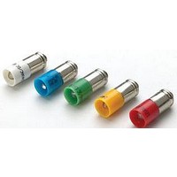
... VAC/DC, 4/8 mA 10-2J19.1046 6 VDC 10-2J06.3146 12 VAC/DC, 4/7 mA 10-2J09.1065 24 VAC/DC, 4/7 mA 10-2J12.1065 28 VAC/DC, 4/7 mA 10-2J13.1065 48 VAC/DC, 2/4 mA 10-2J19.1045 6 VDC 10-2J06.3145 12 VAC/DC, 7/14 mA 10-2J09.1062 24 VAC/DC, 7/14 mA 10-2J12.1062 28 VAC/DC, 7/14 mA 10-2J13.1062 48 VAC/DC, 4/8 mA 10-2J19.1042 6 VDC 10-2J06.3142 12 VAC/DC, 7/14 mA 10-2J09.1069 24 VAC/DC, 7/14 mA 10-2J12.1069 28 VAC/DC, 7/14 mA 10-2J13.1069 48 VAC/DC, 4/8 mA 10-2J19 ...
Page 33
... Mounting tool Dismantling tool Continuation see next page Dismantling tool for dismantling of Lens, Lens holder and Switching element block 51 e Typ-Nr. 31-991 0.005 e Typ-Nr. 51-910 0.001 e Typ-Nr. 61-9730.0 0.011 02-905 0.011 e Typ-Nr. 61-9740.0 0.003 e Typ-Nr. 01-907 0.020 e Typ-Nr. 51-938 0.027 31 01.2010 ...
Page 34
... Accessories Flat receptacle remover Continuation see next page Flat receptacle remover for removing the Flat receptacle of the Multi-plug in housing 32 01.2010 51 e Typ-Nr. 51-943.9 0.001 ...
Page 35
... Shock resistance (Single impacts, semi-sinusoidal for 11 ms, as per IEC 60512-4-3, IEC 60068-2-27 Vibration resistance (Sinusoidal ... 1500 Hz, amplitude 1.5 mm, as per IEC 60512-4- 4, IEC 60068-2-6 Climate resistance Standard condition, as per IEC 60068-2-3 and 2-30 Changing condition, as per IEC 60068-2-14 and 2-33 Approvals ...
Page 36
... Switching system This low level switching element was designed for switching low powers in electronic circuits. The mechanism assures reliable swit- ching of loads ranging from a few μA / μ 100 VAC/ DC. Single-break momentary contact, as normally open or normally closed with 4 independent points of contact. 2 momentary contacts per switching element ...
Page 37
... Electrical characteristics Contact resistance Starting value (initial) ≤50 mΩ Electrostatic breakdown value ≤15 KV (Keylock switch) Switch rating 10 μA, 100 μV to 100 VAC/VDC Electric strength 2500 VAC, 50 Hz, 1 min. between all terminals and earth, as per IEC 60512-2-11 Environmental conditions Storage temperature -40 °C ... +85 °C Service temperature -25 ° ...
Page 38
... Typical Applications Diode element When indicators and illuminated pushbuttons equipped with diodes, the user is able to perform a lamp check or wire an alarm circuit simply with a considerable saving of space 01.2010 51 ...
Page 39
... To get an efficient protection, the free-wheeling diode must be connected as close as possible to the inductive load! 0 Switching with inductive load Fig. 1 Switch + Free-wheeling Inductive VDC _ diode load Counter emf over load without free-wheeling diode Fig OFF 0 Sveral hundred to several thousend volts 01.2010 ...
Page 40
... In the case of use of a smoke-black lens the fitted film becomes readable only if the lamp is on. The film thickness is 0.2 mm. Important : Consider pushbutton mounting orientation befor specifying engraving characters ! Number of (target value) Image small letters per line abc abc abc B4 AB ...
Page 41
... All dimensions Front size Film insert Height of letters (Lens) max. size 15.1 x 15.1 2 ( ( dia. Marking plate 2 (19.7 dia Engraving Number of lines Number of (target value) capital letters per line Film AB abc 51 Number of (target value) Image small letters per line ...
Page 42
... Indicator actuator page 7 | Illuminated pushbutton actuator page 8 | Keylock switch 2 positions page 9 | Selector switch 2 positions page 11 | Indicator actuator, flush mounting page 13 | Illuminated pushbutton actuator, flush mounting page 14 | Keylock switch actuator 2 positions, flush mounting page 15 | Selector switch actuator 2 positions, flush mounting page 19 Terminal (rearside) 40 01.2010 ...
Page 43
... Drawings Mounting dimensions 1 Indicator actuator page 7 | Illuminated pushbutton actuator page 8 | Blind plug, raised mounting page +0 min. 2 Keylock switch 2 positions page 9 | Keylock switch 3 positions page 10 | Selector switch 2 positions page 11 | Selector switch 3 positions page +0 +0. min. 3 Indicator actuator, flush mounting page 13 | Illuminated pushbutton actuator, flush mounting page 14 | Keylock switch actuator ...
Page 44
... Drawings 4 Front bezel set for Mushroom-head pushbutton, flush mounting page 25 Ø Ø Ø min. Ø min. Technical drawing 1 Keylock switch 3 positions page 10 1.5 ... 11 Protective cover, raised mounting page 14.5 3 Protective cover, raised mounting page 14.5 42 01.2010 Ø ...
Page 45
... Drawings 4 Keylock switch actuator 3 positions, flush mounting page 18 1.5 ... 3 Selector switch actuator 3 positions, flush mounting page 20 1.5 ... 9 Selector switch 3 positions page 12 1.5 ... 6 Ø Ø Ø 01.2010 ...
Page 46
... Protective cover, flush mounting page 27 5.5 max 4.5 8 Protective cover, flush mounting page 27 5.5 max 4.5 9 Protective cover, flush mounting page 27 10 29.3 1.5 min. 5.5 max. Ø Legend frame page 24 23 Blind plug, flush mounting page 27 16.5 min. 2 20.5 max. 1... 01.2010 51 ...
Page 47
... Indicator actuator page 7 1.5 ... 10 Illuminated pushbutton actuator page 8 1.5 ... 10 Keylock switch 2 positions page 9 1.5 ... 11 Ø 1D Ø 1NC+1NO 3 2NC+2NO 3NC+3NO 4NC+4NO 1NC+1NO 2NO+2NC+D 1NC, 1NO, 1NC+1NO, 2NC, 2NO Ø 1NC+1NO 2NC+2NO 3NC+3NO 4NC+4NO U 1NC, 1NO, 1NC+1NO, 2NC, 2NO 35.5 45 01.2010 ...
Page 48
... Drawings 15 Indicator actuator, flush mounting page 13 1.5 ... Illuminated pushbutton actuator, flush mounting page 14 1.5 ... Keylock switch actuator 2 positions, flush mounting page 15 1.5 ... 3 01.2010 Ø Ø Ø 1NC+1NO 36 2NC+2NO 3NC+3NO 51 4NC+4NO 1NC, 1NO, 1NC+1NO, 2NC, 2NO 1NC+1NO 35 44.5 - 2NC+2NO 42 3NC+3NO 4NC+4NO 57.5 ...
Page 49
... Illuminated pushbutton actuator page 8 | Illuminated pushbutton actuator, flush mounting page III Illuminated pushbutton actuator page 8 | Illuminated pushbutton actuator, flush mounting page x1 III x2+ Ø 1NC+1NO 2NC+2NO 3NC+3NO 4NC+4NO L1 U 1NC, 1NO, 1NC+1NO, 2NC, 2NO Ø 1NC+1NO 2NC+2NO 39 3NC+3NO 4NC+4NO 54 43.5 1NC+1NO 2NC+2NO 1NC, 1NO, 1NC+1NO, 2NC, 2NO 01.2010 51 ...
Page 50
... Illuminated pushbutton actuator page 8 | Illuminated pushbutton actuator, flush mounting page Illuminated pushbutton actuator page 3(+) 4(-) 9 Illuminated pushbutton actuator page 3(+) 1(-) 4(-) 2(+) 10 Illuminated pushbutton actuator page 8 | Illuminated pushbutton actuator, flush mounting page x1 x2+ 11 Illuminated pushbutton actuator page 8 | Illuminated pushbutton actuator, flush mounting page 01.2010 51 ...
Page 51
... Selector switch 3 positions page 12 | Selector switch actuator 3 positions, flush mounting page Selector switch 3 positions page 12 | Selector switch actuator 3 positions, flush mounting page Selector switch 3 positions page 12 | Selector switch actuator 3 positions, flush mounting page Selector switch 3 positions page 12 | Selector switch actuator 3 positions, flush mounting page 01.2010 ...
Page 52
... Selector switch 2 positions page 11 | Selector switch actuator 2 positions, flush mounting page x2+ 25 Selector switch 2 positions page 11 | Selector switch actuator 2 positions, flush mounting page Selector switch 2 positions page 3(+) 4(-) 27 Selector switch 2 positions page 3(+) 1(-) 4(-) 2(+) 50 01.2010 x1- III x2 x1- III 2 4 x2+ a- 3(+) b+ 4(-) a- 3(+) 1(-) b+ 4(-) 2(+) x1- 51 ...
Page 53
... Selector switch 2 positions page 11 | Selector switch actuator 2 positions, flush mounting page Selector switch 2 positions page 11 | Selector switch actuator 2 positions, flush mounting page Selector switch 2 positions page 11 | Selector switch actuator 2 positions, flush mounting page Selector switch 2 positions page 11 | Selector switch actuator 2 positions, flush mounting page x1- III x2 x1- III 01.2010 ...
Page 54
... Selector switch 2 positions page 3(+) 4(-) 41 Selector switch 2 positions page 3(+) 1(-) 4(-) 2(+) 42 Selector switch 2 positions page 11 | Selector switch actuator 2 positions, flush mounting page x1 x2+ 43 Selector switch 2 positions page 11 | Selector switch actuator 2 positions, flush mounting page 01.2010 a- 3(+) b+ 4(-) a- 3(+) 1(-) b+ 4(-) 2(+) x1- 51 ...
Page 55
... Selector switch 2 positions page 11 | Selector switch actuator 2 positions, flush mounting page Illuminated pushbutton actuator page 8 | Illuminated pushbutton actuator, flush mounting page III Illuminated pushbutton actuator page 8 | Illuminated pushbutton actuator, flush mounting page x1 III x2+ 50 Illuminated pushbutton actuator page 3(+) 4(-) 51 Illuminated pushbutton actuator page 3(+) 1(-) 4(-) 2(+) 01.2010 ...
Page 56
... Illuminated pushbutton actuator page 8 | Illuminated pushbutton actuator, flush mounting page x1 x2+ 57 Illuminated pushbutton actuator page 8 | Illuminated pushbutton actuator, flush mounting page Illuminated pushbutton actuator page 8 | Illuminated pushbutton actuator, flush mounting page Illuminated pushbutton actuator page 8 | Illuminated pushbutton actuator, flush mounting page 01.2010 51 ...
Page 57
... Keylock switch 3 positions page 10 | Keylock switch actuator 3 positions, flush mounting page Keylock switch 3 positions page 10 | Keylock switch actuator 3 positions, flush mounting page Keylock switch 2 positions page 9 | Keylock switch actuator 2 positions, flush mounting page Keylock switch 2 positions page 9 | Keylock switch actuator 2 positions, flush mounting page 15 ...
Page 58
... Keylock switch 2 positions page 9 | Keylock switch actuator 2 positions, flush mounting page Keylock switch 2 positions page 9 | Keylock switch actuator 2 positions, flush mounting page Keylock switch 2 positions page 9 | Keylock switch actuator 2 positions, flush mounting page Keylock switch 2 positions page 9 | Keylock switch actuator 2 positions, flush mounting page 01.2010 1 3 III III III III ...
Page 59
... Drawings 76 Keylock switch 2 positions page 9 | Keylock switch actuator 2 positions, flush mounting page Keylock switch 2 positions page 9 | Keylock switch actuator 2 positions, flush mounting page Indicator actuator page 7 a-(x1) 3(+) b+(x2) 4(-) 79 Indicator actuator page 7 a-(x1) 3(+) 1(-) b+(x2) 4(-) 2(+) 51 57 01.2010 ...
Page 60
... 02-912.2 .....................................30 02-912.3 .....................................30 02-912.4 .....................................30 10-1306.1349 .............................29 10-1307.1369 .............................29 10-1309.1309 .............................29 10-1310.1319 .............................29 10-1311.1249 .............................29 10-1312.1229 .............................29 10-1313.1209 .............................29 10-1313.1249 .............................29 10-1316.1179 .............................29 10-1316.1209 .............................29 10-1319.1179 .............................29 10-1319.1199 .............................29 10-2J06.3142 .............................30 10-2J06.3144 .............................30 10-2J06.3145 .............................30 10-2J06.3146 .............................30 10-2J06.3149 .............................30 10-2J09.1062 .............................30 10-2J09.1064 .............................30 10-2J09.1065 .............................30 10-2J09.1066 .............................30 10-2J09.1069 .............................30 10-2J12.1062 .............................30 10-2J12.1064 .............................30 10-2J12.1065 .............................30 10-2J12.1066 .............................30 10-2J12.1069 .............................30 10-2J13.1062 .............................30 10-2J13.1064 .............................30 10-2J13.1065 .............................30 10-2J13.1066 .............................30 10-2J13.1069 .............................30 10-2J19.1042 .............................30 10-2J19.1044 .............................30 10-2J19.1045 .............................30 10-2J19.1046 .............................30 10-2J19.1049 .............................30 31-928 ........................................29 31-929 ...
Page 61
... Typ-Nr. Page 51-385.022D .............................. 10 51-385.022DF ............................ 18 51-386.022D .............................. 10 51-386.022DF ............................ 18 51-387.022D .............................. 10 51-387.022DF ............................ 18 51-388.022D .............................. 10 51-388.022DF ............................ 18 51-395.022D ................................ 9 51-395.022DF ............................ 16 51-395.025D2 .............................. 9 51-395.025D2F .......................... 16 51-396.025D2 .............................. 9 51-396 ...
Page 62
... Typ-Nr. Page 51-933.4 .....................................21 51-933.5 .....................................21 51-933.6 .....................................21 51-933 ...
Page 63
... Typ-Nr. Page 61 01.2010 ...
Page 64
... Fax +41 62 388 95 55 E-mail sales.ech@eao.com United Kingdom Phone +44 1444 236 000 Fax +44 1444 236 641 E-mail sales.euk@eao.com USA Phone +1 203 877 4577 Fax +1 203 877 3694 E-mail sales.eus@eao.com Other Countries Phone +41 62 286 92 10 Fax +41 62 296 21 62 E-mail info@eao.com ...